74 Rockwell Automation Publication 1734-UM013C-EN-P - August 2010
Chapter 6 Configure the Module in a GuardLogix Controller
6. In the Safety Network Number box, use the default setting.
For a detailed explanation of the safety network number (SNN), see the
GuardLogix Controller Systems Safety Reference Manual, publication
1756-RM093
, noting that in most cases, you use the default provided by
the RSLogix 5000 software.
The purpose of the Safety Network Number (SNN) is to make sure that
every module in a system can be uniquely identified. We suggest that all
safety modules on a network have the same SNN, to make documentation
easier. During configuration, RSLogix 5000 software defaults a safety
device’s SNN to match the SNN of the lowest safety node on the network.
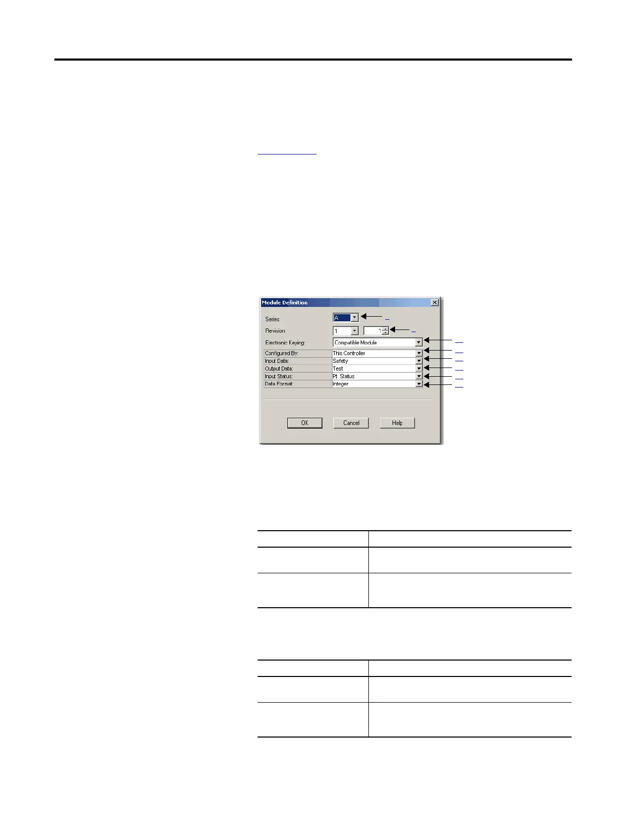
7. Click Change to edit the Module Definition.
This Module Definition dialog box appears.
8. In the Series box, enter the input module’s series letter.
9. In the Revision boxes, enter the input module’s revision numbers.
10. From the Electronic Keying pull-down menu, choose the appropriate
keying method for the input module.
11. From the Configured By pull-down menu, choose the appropriate method
by which this module is configured.
Choose Description
Exact Match All of the parameters must match or the inserted module
rejects a connection to the controller.
Compatible Module Allows an I/O module to determine whether it can emulate
the module defined in the configuration sent from the
controller.
Choose Description
This Controller This selection directs the controller to configure the Inputs
and Test Outputs.
External Means This selection directs the controller to establish a safety
input connection only, and the controller will not configure
the module or control the Test Outputs.

 Loading...


