92 Rockwell Automation Publication 1734-UM013C-EN-P - August 2010
Chapter 6 Configure the Module in a GuardLogix Controller
Configure the
Test Output Tab
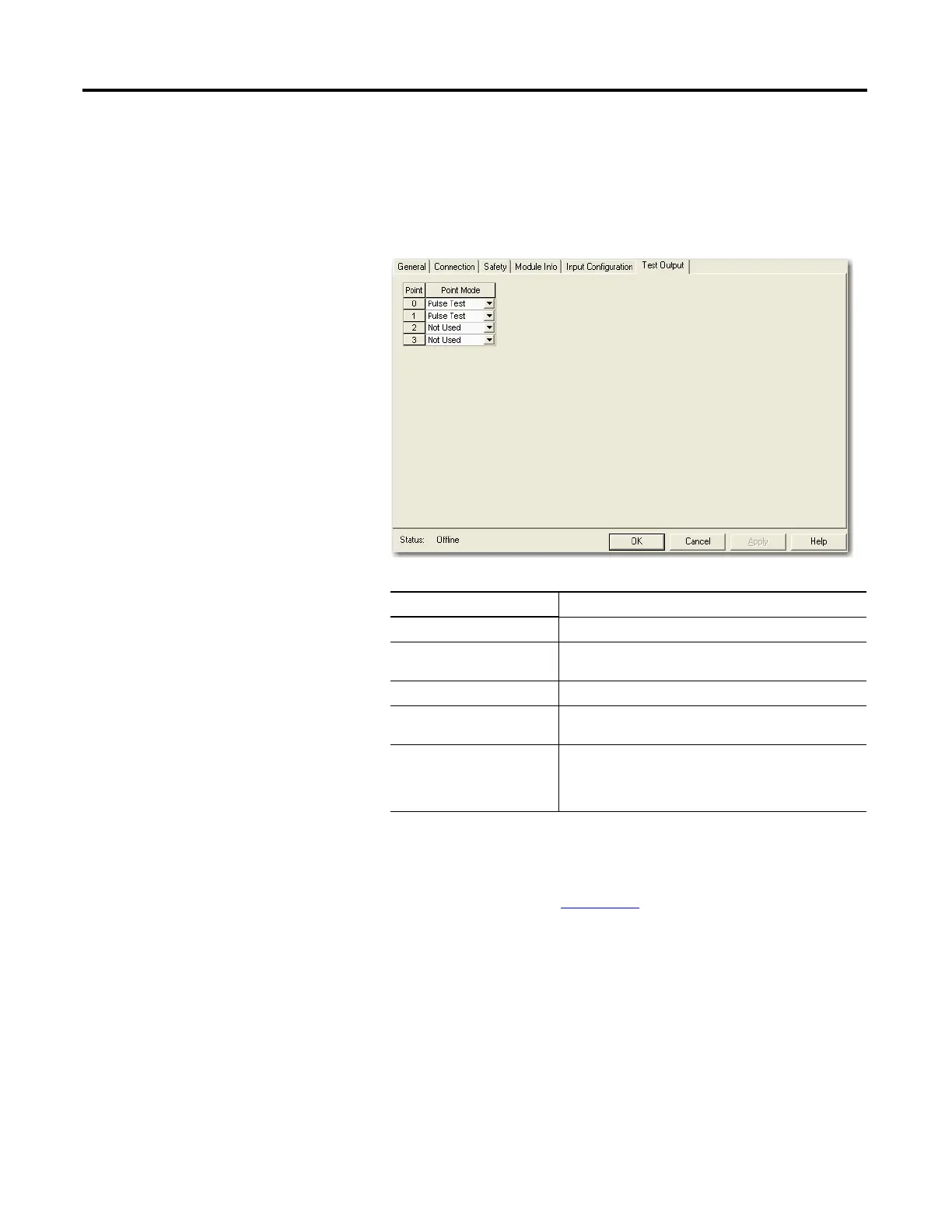
This section describes how to work with the Test Output Configuration dialog
box. Refer to this table for information on configuring test outputs.
Follow this procedure to complete the test output configuration.
1. From the Module Properties dialog box, click the Test Output tab.
2. Assign the Point Mode.
There is also a Test Output Fault Action parameter that can only be read or
written to via explicit messaging. If communication to the module times
out, you can set the test outputs to Clear OFF (default) or Hold Last State.
For more information, see Appendix A
.
3. Click Apply.
Choose Description
Not Used (default) The test output is disabled.
Standard The test output point can be controlled programmatically
by the GuardLogix controller.
Pulse Test The test output is being used as a pulse test source.
Power Supply A constant 24V is placed on the output terminal. It can be
used to provide power to a field device.
Muting Lamp Output (terminal
T1 and T3 only)
An indicator lamp is connected to the output. When this
lamp is energized, a burned-out bulb, broken wire, or short
to GND error condition can be detected. Typically, the lamp
is an indicator used in light curtain applications.

 Loading...


