122 Rockwell Automation Publication 2080-UM002G-EN-E - March 2015
Chapter 8 Use the High-Speed Counter and Programmable Limit Switch
HSC0's sub counter is HSC1, HSC2's sub counter is HSC3 and HSC4's sub
counter is HSC5. Each set of counters share the input. The following table shows
the dedicated inputs for the HSCs depending on the mode.
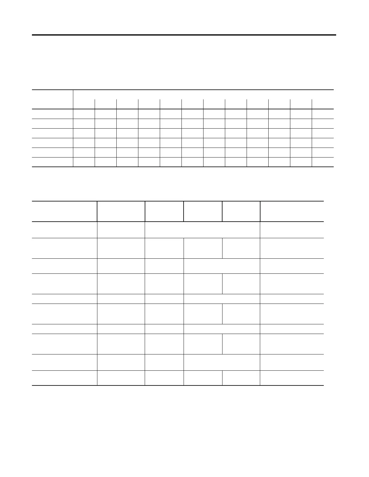
The following tables show the input wiring mapping for the different Micro830
and Micro850 controllers.
HSC Input Wiring Mapping
Embedded Input
0 0102030405060708091011
HSC0 A/C B/D Reset Hold
HSC1 A/C B/D
HSC2 A/C B/D Reset Hold
HSC3 A/C B/D
HSC4 A/C B/D Reset Hold
HSC5 A/C B/D
Micro830 10 and 16-point Controller HSC Input Wiring Mapping
Modes of Operation Input 0 (HSC0)
Input 2 (HSC1)
Input 1 (HSC0)
Input 3 (HSC1)
Input 2 (HSC0) Input 3 (HSC0) Mode Value in
User Program
(HSCAppData.HSCMode)
Counter with Internal Direction
(mode 1a)
Count Up Not Used 0
Counter with Internal
Direction, External Reset and
Hold (mode 1b)
Count Up Not Used Reset Hold 1
Counter with External
Direction (mode 2a)
Count Up/Down Direction Not Used 2
Counter with External
Direction, Reset and Hold
(mode 2b)
Count Direction Reset Hold 3
Two Input Counter (mode 3a) Count Up Count Down Not Used 4
Two Input Counter with
External Reset and Hold (mode
3b)
Count Up Count Down Reset Hold 5
Quadrature Counter (mode 4a) A Type input B Type input Not Used 6
Quadrature Counter with
External Reset and Hold (mode
4b)
A Type input B Type input Z Type Reset Hold 7
Quadrature X4 Counter
(mode 5a)
A Type input B Type input Not Used 8
Quadrature X4 Counter with
External Reset and Hold
A Type input B Type input Z Type Reset Hold 9

 Loading...


