Rockwell Automation Publication 2080-UM002G-EN-E - March 2015 7
Hardware Overview Chapter 1
Embedded Serial Port Cables
Embedded serial port cables for communication are listed here. All embedded
serial port cables must be 3 meters in length, or shorter.
Embedded Ethernet Support
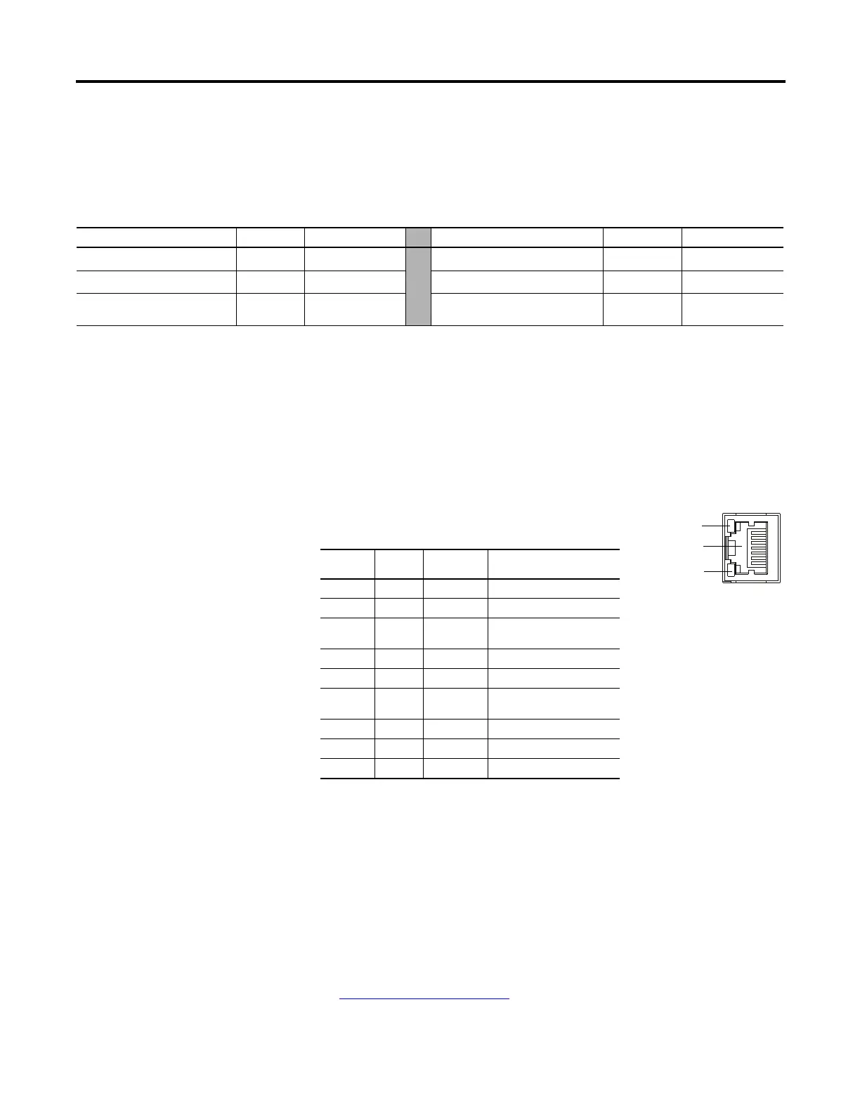
For Micro850 controllers, a 10/100 Base-T Port (with embedded green and
yellow LED indicators) is available for connection to an Ethernet network
through any standard RJ-45 Ethernet cable. The LED indicators serve as
indicators for transmit and receive status.
Micro850 controllers support Ethernet crossover cables (2711P-CBL-EX04).
Ethernet Status Indication
Micro850 controllers also support two LEDs for EtherNet/IP to indicate the
following:
• Module status
• Network status
See Troubleshooting
on page 243 for descriptions of Module and Network status
indicators.
Embedded Serial Port Cable Selection Chart
Connectors Length Cat. No. Connectors Length Cat. No.
8-pin Mini DIN to 8-pin Mini DIN 0.5 m (1.5 ft)
1761-CBL-AM00
(1)
8-pin Mini DIN to 9-pin D Shell 0.5 m (1.5 ft)
1761-CBL-AP00
(1)
8-pin Mini DIN to 8-pin Mini DIN 2 m (6.5 ft)
1761-CBL-HM02
(1)
8-pin Mini DIN to 9-pin D Shell 2 m (6.5 ft)
1761-CBL-PM02
(1)
8-pin Mini DIN to 6-pin RS-485
terminal block
30 cm (11.8in.) 1763-NC01 series A
(1) Series C or later for Class 1 Div 2 applications.
yellow LED
green LED
RJ-45 connector
RJ-45 Ethernet Port Pin Mapping
Contact
Number
Signal Direction Primary Function
1 TX+ OUT Transmit data +
2 TX- OUT Transmit data -
3 RX+ IN Differential Ethernet Receive
Data +
4 Terminated
5 Terminated
6 RX- IN Differential Ethernet Receive
Data -
7 Terminated
8 Terminated
Shield Chassis Ground
45920
The yellow status LED
indicates Link (solid yellow)
or No Link (off).
The green status LED
indicates activity (blinking
green) or no activity (off).

 Loading...


