Rockwell Automation Publication 2080-UM002G-EN-E - March 2015 35
Chapter
4
Wire Your Controller
This chapter provides information on the Micro830 and Micro850 controller
wiring requirements. It includes the following sections:
Wiring Requirements and
Recommendation
• Allow for at least 50 mm (2 in.) between I/O wiring ducts or terminal
strips and the controller.
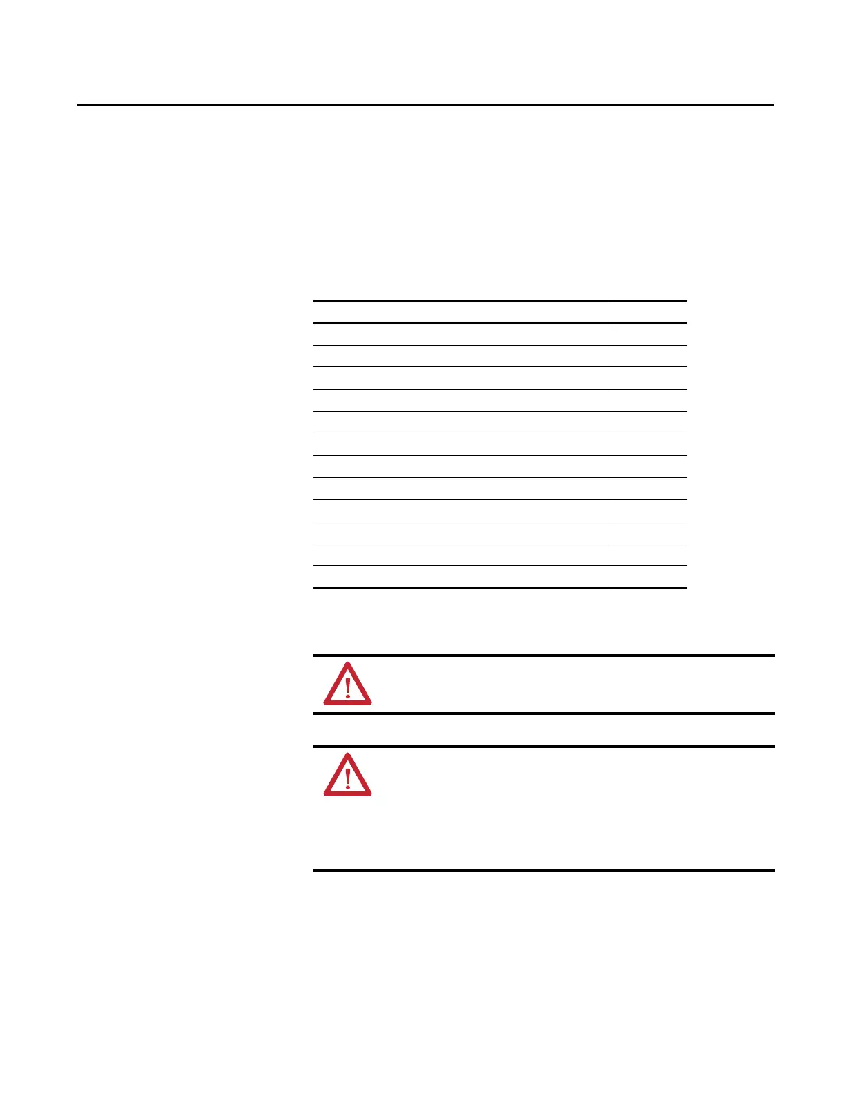
Topic Page
Wiring Requirements and Recommendation 35
Use Surge Suppressors 36
Recommended Surge Suppressors 38
Grounding the Controller 39
Wiring Diagrams 39
Controller I/O Wiring 42
Minimize Electrical Noise 43
Analog Channel Wiring Guidelines 43
Minimize Electrical Noise on Analog Channels 43
Grounding Your Analog Cable 44
Wiring Examples 44
Embedded Serial Port Wiring 45
WARNING: Before you install and wire any device, disconnect power to
the controller system.
WARNING: Calculate the maximum possible current in each power and
common wire. Observe all electrical codes dictating the maximum
current allowable for each wire size. Current above the maximum ratings
may cause wiring to overheat, which can cause damage.
United States Only: If the controller is installed within a potentially
hazardous environment, all wiring must comply with the requirements
stated in the National Electrical Code 501-10 (b).

 Loading...


