Rockwell Automation Publication 2080-UM002G-EN-E - March 2015 5
Hardware Overview Chapter 1
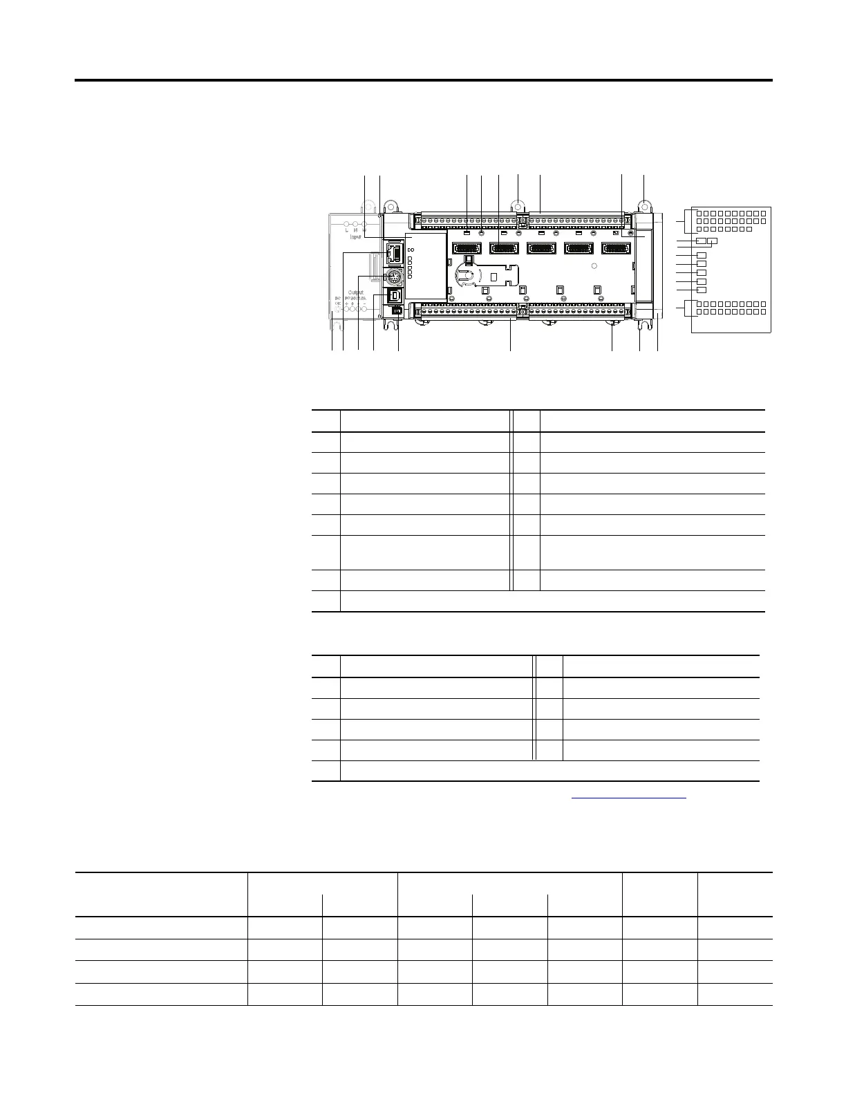
Controller Description
Description Description
1 Status indicators 9 Expansion I/O slot cover
2 Optional power supply slot 10 DIN rail mounting latch
3 Plug-in latch 11 Mode switch
4 Plug-in screw hole 12 Type B connector USB port
5 40-pin high speed plug-in connector 13 RS232/RS485 non-isolated combo serial port
6 Removable I/O terminal block 14 RJ-45 EtherNet/IP connector (with embedded yellow
and green LED indicators)
7 Right-side cover 15 Optional AC power supply
8 Mounting screw hole / mounting foot
Status Indicator Description
(1)
(1) For detailed descriptions of these LED status indicators, see Troubleshooting
on page 243.
Description Description
16 Input status 21 Fault status
17 Module status 22 Force status
18 Network status 23 Serial communications status
19 Power status 24 Output status
20 Run status
45915
45918
Status indicators
1
2
3
4
5
8
6
8
7
9
8
10
6
11
12
13
14
15
Micro850 48-point controllers and status indicators
Micro830 Controllers – Number and Type of Inputs/Outputs
Catalog Number Inputs Outputs PTO Support HSC Support
110V AC 24V DC/V AC Relay 24V Sink 24V Source
2080-LC30-10QWB 6 4 2
2080-LC30-10QVB 6 4 1 2
2080-LC30-16AWB 10 6
2080-LC30-16QWB 10 6 2

 Loading...


