Rockwell Automation Publication 2080-UM002K-EN-E - March 2019 87
Motion Control Chapter 7
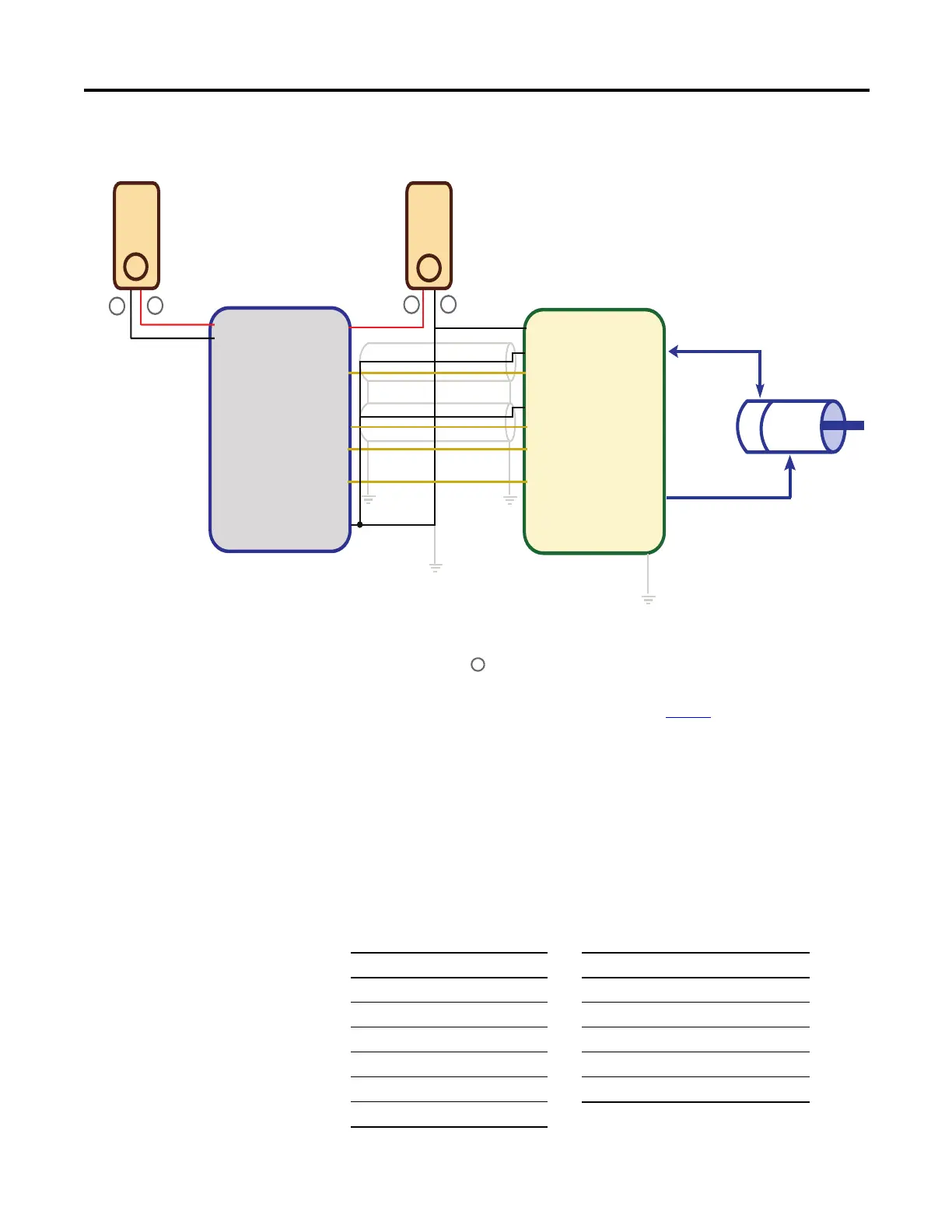
Sample Motion Wiring Configuration on 2080-LC30-xxQBB / 2080-LC50-xxQBB /
2080-LC70-xxQBB
Motion Control Function
Blocks
Motion control function blocks instruct an axis to a specified position, distance,
velocity, and state.
Function Blocks are categorized as Movement (driving motion) and
Administrative.
2080-LC30-xxQBB
2080-LC50-xxQBB
Kinetix3
+DC 24
-DC 24
+CM0
+CM1
O-00
O-03
O-06
O-07
-CM0
-CM1
Pin 1, 2
Pin 12(CLK-)
Pin 49(CLK+)
Pin 14(DIR-)
Pin 25(DIR+)
Pin 3(Enable)
Pin 7(RST)
1
2
24V
Power
Supply
24V
Power
Supply
–
_
Encoder
Motor
Encoder signal cable
Motor power cable
+
+
Notes:
(1) Drive Enable (Pin 3) and Reset Drive (Pin 7) will be operating as sinking inputs when (Pin 1,2)
connected to + of the Power Supply 2.
46047
(2) To help you configure Kinetix3 drive parameters so the drive can communicate and be controlled by a
Micro830/Micro850/Micro870 controller, see publication CC-QS033
. The parameter Command Type
must be set to “Step/Direction.Positive Logic”, and the parameter Controller Output Type must be set to
“Open Collector Input”.
Administrative Function Blocks
Function Block Name Function Block Name
MC_Power MC_ReadAxisError
MC_Reset MC_ReadParameter
MC_TouchProbe MC_ReadBoolParameter
MC_AbortTrigger MC_WriteParameter
MC_ReadStatus MC_WriteBoolParameter
MC_SetPosition
 Loading...


