144 Rockwell Automation Publication 2080-UM002K-EN-E - March 2019
Chapter 8 Use the High-Speed Counter and Programmable Limit Switch
Using the Quadrature Encoder
The Quadrature Encoder is used for determining direction of rotation and
position for rotating, such as a lathe. The Bidirectional Counter counts the
rotation of the Quadrature Encoder.
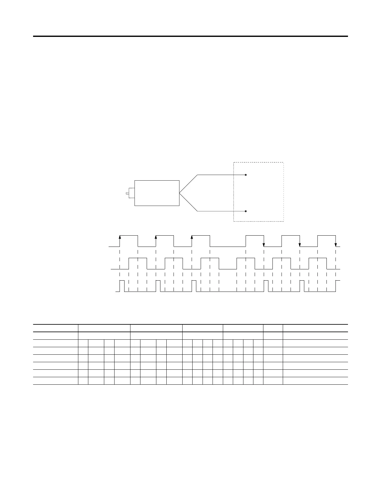
The figure below shows a quadrature encoder connected to inputs 0, 1, and 2.
The count direction is determined by the phase angle between A and B. If A leads
B, the counter increments. If B leads A, the counter decrements.
The counter can be reset using the Z input. The Z outputs from the encoders
typically provide one pulse per revolution.
HSC Mode 6 – Quadrature Counter (phased inputs A and B)
Reverse Rotation
Forward Rotation
B
A
1
2
3
2
1
Count
Input 0
Input 1
Input 2
A
B
Z
Reset
Quadrature Encoder
A
B
Input 0
Input 1
HSC Mode 6 Examples
Input Terminals Embedded Input 0 Embedded Input 1 Embedded Input 2 Embedded Input 3 CE Bit Comments
Function Count A Count B Not Used Not Used
Example 1
(1)
off (0) on (1) HSC Accumulator + 1 count
Example 2
(2)
off (0) on (1) HSC Accumulator - 1 count
Example3 off (0) Hold accumulator value
Example 4 on (1) Hold accumulator value
Example 5 on (1) Hold accumulator value
Example 6 off (0) Hold accumulator value
(1) Count input A leads count input B.
(2) Count input B leads count input A.
Blank cells = don’t care,
= rising edge, = falling edge
Inputs 0…11 are available for use as inputs to other functions regardless of the HSC being used.
 Loading...


