48 Rockwell Automation Publication 2080-UM002K-EN-E - March 2019
Chapter 4 Wire Your Controller
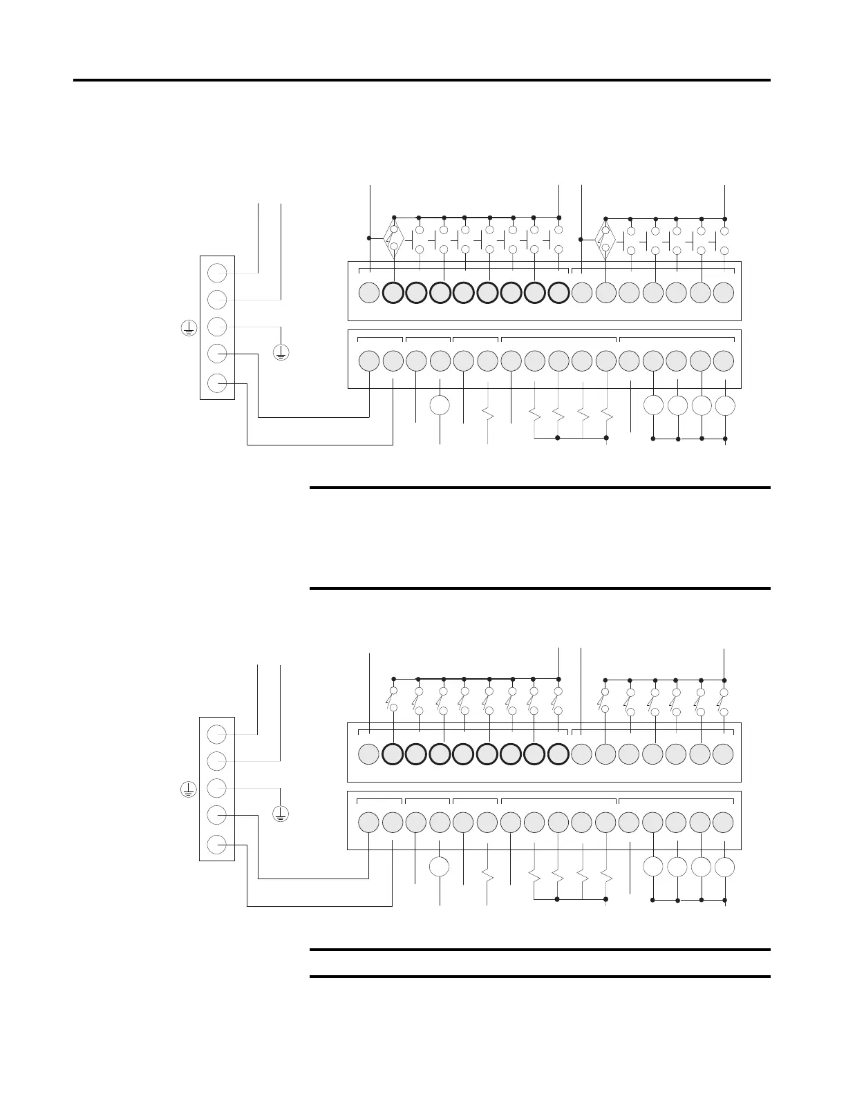
2080-LC30-24QWB, 2080-LC50-24QWB, 2080-LC70-24QWB, 2080-LC70-24QWBK,
DC Input Configuration
2080-LC50-24AWB, 2080-LC70-24AWB, DC Input Configuration
I-00
COM0 I-01
I-02
I-03
I-04
I-05
I-06 COM1
I-07
I-09
I-08
123456789101112
+DC24 CM0
O-00-DC24
CM1
O-01
CM2
O-02 O-04
O-03
CM3
O-05
123456789101112
I-11
I-10
I-13
I-12
13 14 15 16
O-07
O-06
O-09
O-08
13 14 15 16
-24 VDC
+24 VDC
N
L
L1 L2
2080-PS120-240VAC
Sourcing:+DC b
Sinking: -DC b
Sourcing:-DC b
Sinking: +DC b
Sourcing:+DC a
Sinking: -DC a
Sourcing:-DC a
Sinking: +DC a
-DC c
CR
CR CR
CR
+DC c
L2 c
L1 cL1 b
+DC c
CR
-DC c
L2 b
• Do not connect –DC24 (Output terminal 2) to Earth/Chassis Ground.
• In Micro870 systems that use more than four Micro800 Expansion
I/O modules, we recommend to use a 1601-XLP60EQ power supply
instead of a 2080-PS120-240VAC power supply. Make sure to wire
both the Micro870 controller and 2085-EP24VDC expansion power
supply to the same 1601-XLP60EQ power supply.
I-00
COM0 I-01
I-02
I-03
I-04
I-05
I-06 COM1
I-07
I-09
I-08
123456789101112
+DC24 CM0
O-00-DC24
CM1
O-01
CM2
O-02 O-04
O-03
CM3
O-05
123456789101112
I-11
I-10
I-13
I-12
13 14 15 16
O-07
O-06
O-09
O-08
13 14 15 16
-24 VDC
+24 VDC
N
L
L1 L2
2080-PS120-240VAC
L2 a
-DC c
CR
CR CR
CR
+DC c
L2 c
L1 cL1 b
+DC c
CR
-DC c
L2 b
L1 a
L2 b
L1 b
Do not connect –DC24 (Output terminal 2) to Earth/Chassis Ground.
 Loading...


