1-2 Installation/Wiring
PowerFlex 4M Adjustable Frequency Drive FRN 1.xx - 2.xx User Manual
Publication 22F-UM001D-EN-E
• Mount the drive upright on a flat, vertical and level surface.
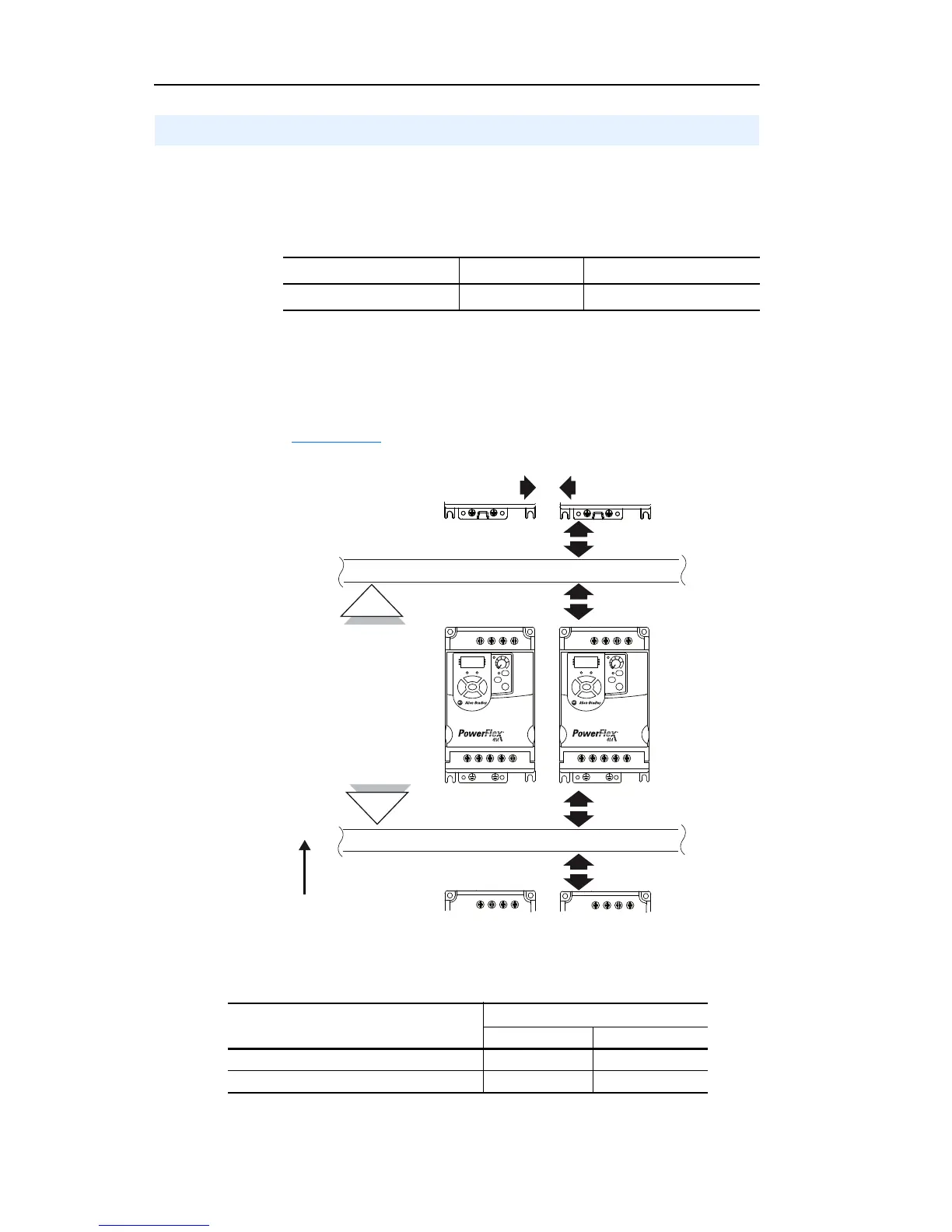
– Install on 35 mm DIN Rail (for frames A and B).
or
– Install with screws.
Table 1.A Screw Mounting Recommendations
• Protect the cooling fan by avoiding dust or metallic particles.
• Do not expose to a corrosive atmosphere.
• Protect from moisture and direct sunlight.
Minimum Mounting Clearances
Refer to Appendix B for mounting dimensions.
Ambient Operating Temperatures
Drive enclosure is rated IP20, NEMA/UL Type Open.
Mounting Considerations
Minimum Panel Thickness Screw Size Mounting Torque
1.9 mm (0.0747 in.) M4 (#8-32) 1.56-1.96 N-m (14-17 lb.-in.)
Table 1.B Enclosure and Clearance Requirements
Horizontal Clearance between drives
Ambient Temperature
Minimum Maximum
0 mm and greater -10°C (14°F) 40°C (104°F)
25 mm and greater -10°C (14°F) 50°C (122°F)
 Loading...


