Installation/Wiring 1-11
PowerFlex 4M Adjustable Frequency Drive FRN 1.xx - 2.xx User Manual
Publication 22F-UM001D-EN-E
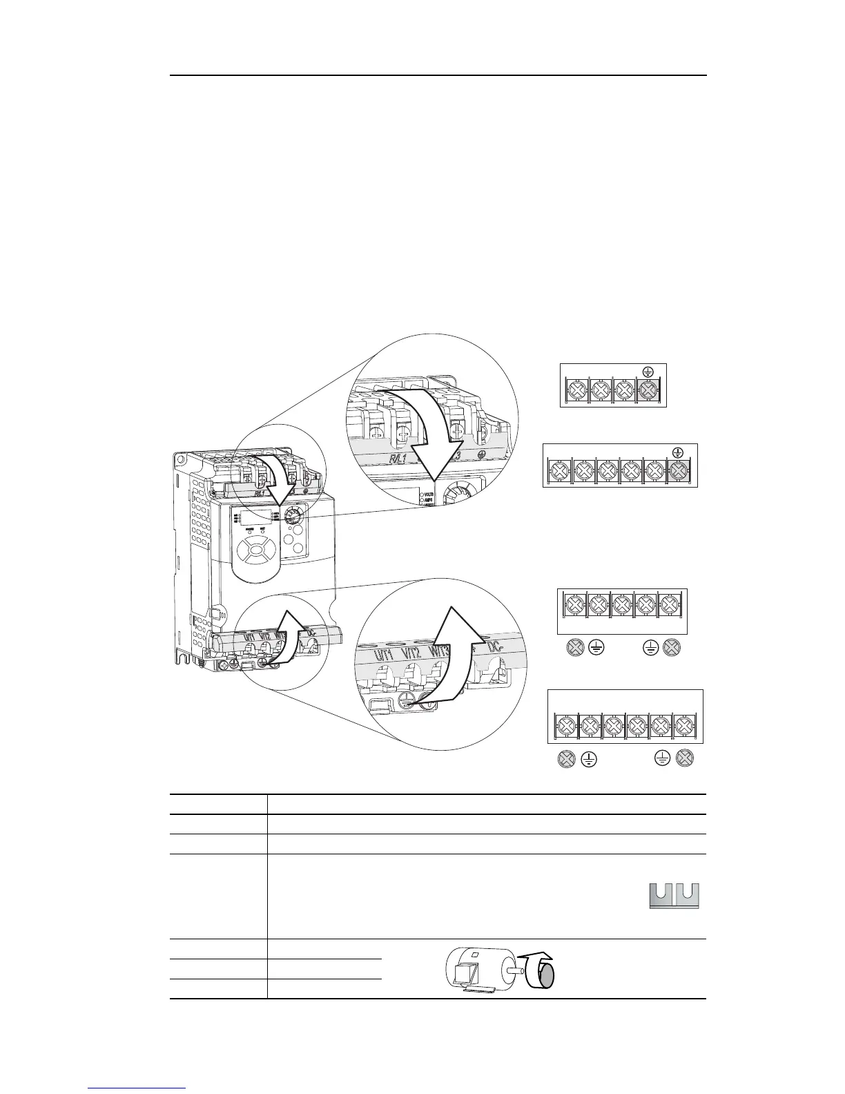
Power Terminal Block
The drive utilizes a finger guard over the power wiring terminals.
To remove:
1. Press in and hold the locking tab.
2. For the finger guard on the top of the drive, slide it down and out.
For the finger guard at the bottom of the drive, slide it up and out.
Replace the finger guard when wiring is complete.
Figure 1.4 Power Terminal Block
T/L3S/L2R/L1
P1
P2
Frame C
Frame A and B
T/L3S/L2R/L1
W/T3V/T2U/T1
DC-BR-
BR+
DC+
Frame C
W/T3V/T2U/T1
DC+
DC-
Frame A and B
Terminal Description
R/L1, S/L2 1-Phase Input
R/L1, S/L2, T/L3 3-Phase Input
P1
(1)
, P2
(1)
DC Bus Inductor Connection (Frame C drives only.)
The Frame C drive is shipped with a jumper between Terminals P1
and P2. Remove this jumper only when a DC Bus Inductor will be
connected. Drive will not power up without a jumper or inductor
connected.
U/T1 To Motor U/T1
=
Switch any two motor
leads to change forward
direction.
V/T2 To Motor V/T2
W/T3 To Motor W/T3

 Loading...


