Installation/Wiring 1-15
PowerFlex 4M Adjustable Frequency Drive FRN 1.xx - 2.xx User Manual
Publication 22F-UM001D-EN-E
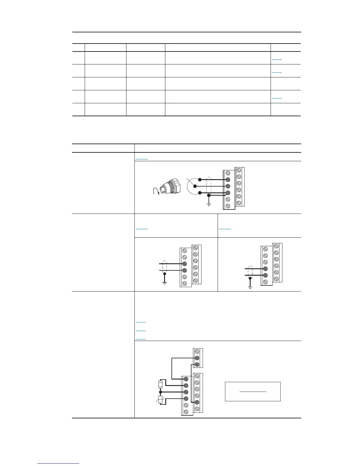
I/O Wiring Examples
12 +10V DC –
Drive supplied power for 0-10V external potentiometer.
Maximum output current is 15mA.
P108
13 0-10V In
(3)
Not Active
For external 0-10V input supply
(input impedance = 100k ohm) or potentiometer wiper.
P108
14 Analog Common –
For 0-10V In or 4-20mA In. Electronically isolated with
analog inputs from digital I/O.
15 4-20mA In
(3)
Not Active
For external 4-20mA input supply
(input impedance = 250 ohm).
P108
16 RS485 (DSI) Shield –
Terminal should be connected to safety ground - PE
when using the RS485 (DSI) communications port.
(3)
Only one analog frequency source may be connected at a time. If more than one reference is connected at the same
time, an undetermined frequency reference will result.
No. Signal Default Description Param.
Input Connection Example
Potentiometer
1-10k Ohm Pot.
Recommended
(2 Watt minimum)
P108
[Speed Reference] = 2 “0-10V Input”
Analog Input
0 to +10V, 100k ohm
impedance
4-20 mA, 100 ohm
impedance
Voltage
P108
[Speed Reference] = 2 “0-10V
Input”
Current
P108 [Speed Reference] = 3
“4-20mA Input”
Analog Input, PTC
For Drive Fault
Wire the PTC and External Resistor (typically matched to the PTC Hot
Resistance) to I/O Terminals 12, 13, 14.
Wire R2/R3 Relay Output (SRC) to I/O Terminals 5 & 11.
t201
[Digital In1 Sel] = 3 “Aux Fault”
t221
[Relay Out Sel] = 10 “Above Anlg V”
t222
[Relay Out Level] = % Voltage Trip
12
13
14

 Loading...


