Programming and Parameters 3-5
PowerFlex 4M Adjustable Frequency Drive FRN 1.xx - 2.xx User Manual
Publication 22F-UM001D-EN-E
Display Group (continued)
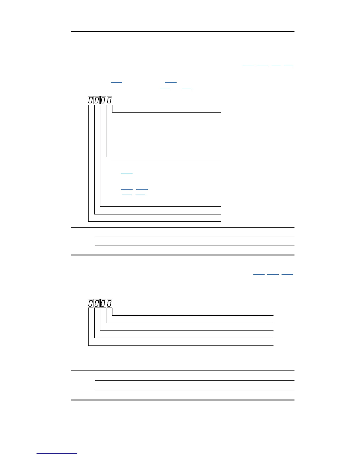
d012 [Control Source] Related Parameter(s): P106, P108, t201, t202
Displays the active source of the Start Command and Speed Command which are normally defined
by the settings of
P106 [Start Source] and P108 [Speed Reference] but may be overridden by digital
inputs. Refer to the flowcharts on pages
1-19 and 1-20 for details.
Values Default Read Only
Min/Max: 0/9
Display: 1
Start Command Digit 0
0 = Keypad
1 = 3-Wire
2 = 2-Wire
3 = 2-Wire Level Sensitive
4 = 2-Wire High Speed
5 = RS485 (DSI) Port
9 = Jog
Speed Command Digit 1
0 = Drive Potentiometer
1 =
A409 [Internal Freq]
2 = 0-10V Input/Remote Potentiometer
3 = 4-20mA Input
4 =
A410 - A413 [Preset Freq x]
(
t201 - t202 [Digital Inx Sel] must be set to 4)
5 = RS485 (DSI) Port
9 = Jog Freq
Reserved Digit 2
Reserved Digit 3
d013 [Contrl In Status] Related Parameter(s): d002, P104, P105
Status of the control terminal block control inputs.
Important: Ac
tual control commands may come from a source other than the control terminal block.
Values Default Read Only
Min/Max: 0/1
Display: 1
1 = Input Present, 0 = Input Not Present
Start / Run FWD Input (I/O Terminal 02) Bit 0
Direction / Run REV Input (I/O Terminal 03) Bit 1
Stop Input
(1)
(I/O Terminal 01) Bit 2
(1)
The stop input must be present in order to start the drive.
When this bit is a 1 the drive can be started.
When this bit is a 0 the drive will stop.
Dynamic Brake Transistor ON (Frame C only) / Reserved (Other Frames) Bit 3

 Loading...


