Rockwell Automation Publication 520-UM001A-EN-E - February 2013 203
PID Set Up Appendix F
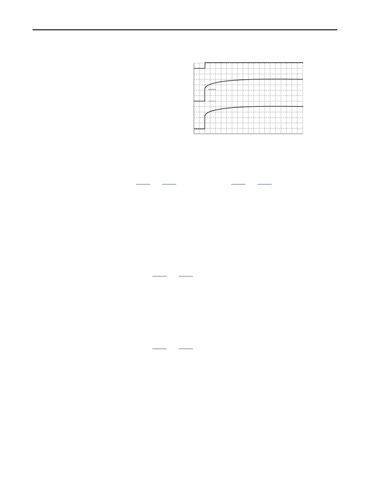
drive’s frequency command to initially jump to that preload frequency, and the
PID loop starts regulating from there.
PID Limits
A456 and A468 [PID x Trim Hi] and A457 and A469 [PID x Trim Lo] are used
to limit the PID output and are only used in trim mode. [PID x Trim Hi] sets the
maximum frequency for the PID output in trim mode. [PID x Trim Lo] sets the
reverse frequency limit for the PID output in trim mode. Note that when the
PID reaches the Hi or Lo limit, the PID regulator stops integrating so that
windup does not occur.
PID Gains
The proportional, integral, and differential gains make up the PID regulator.
• A461
and A473 [PID x Prop Gain]
The proportional gain (unitless) affects how the regulator reacts to the
magnitude of the error. The proportional component of the PID regulator
outputs a speed command proportional to the PID error. For example, a
proportional gain of 1 would output 100% of max frequency when the
PID error is 100% of the analog input range. A larger value for [PID x
Prop Gain] makes the proportional component more responsive, and a
smaller value makes it less responsive. Setting [PID x Prop Gain] to 0.00
disables the proportional component of the PID loop.
• A462
and A474 [PID x Integ Time]
The integral gain (units of seconds) affects how the regulator reacts to
error over time and is used to get rid of steady state error. For example, with
an integral gain of 2 seconds, the output of the integral gain component
would integrate up to 100% of max frequency when the PID error is 100%
for 2 seconds. A larger value for [PID x Integ Time] makes the integral
component less responsive, and a smaller value makes it more responsive.
Setting [PID x Integ Time] to 0.0 disables the integral component of the
PID loop.
PID Enabled
Freq Cmd
PID Output
PID Pre-load Value
PID Pre-load Value > 0

 Loading...


