1. Arrange the sections as directed in the Dimensional Drawings and move
2. Align the cabinet side sheets together at the holes for the hardware
).
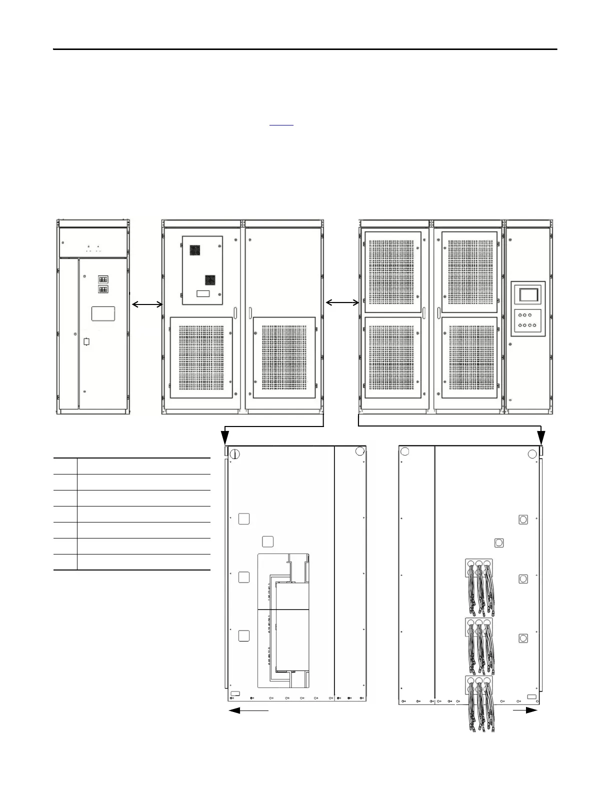
Isolation Transformer Cabinet
Power Module/LV Control Cabinet
Optional Cabinets
1. Start-up cabinet (Pre-charge cabinet)
2. Output filter cabinet
3. Bypass cabinet
4. and others
Table 1 - Sidesheet Openings
❶
Front Wireway
❷
U Phase Motor Cable
❸
V Phase Motor Cable
❹
W Phase Motor Cable
❺
Ground Bus Connection
❻
Voltage Sensing Board Cables
❼
Isolation Transformer Secondary Cables
(1)
(1) The number of Isolation Transformer secondary cables is
dependent on motor voltage class.
• 9 cables per motor phase (27 total) for 3/3.3 kV
•12 cables per motor phase (36 total) for 4.16 kV
• 15 cables per motor phase (45 total) for 6 kV
•18 cables per motor phase (54 total) of 6.6 kV
•24 cables per motor phase (72 total) for 10kV
• 27 cables per motor phase (81 total) for 11 kV
❶
❷
❸
❼
❹
❺
❻
❶
❸
❼
❹
❺
❻
Front
Front
❷
Side View

 Loading...


