EasyManuals Logo
Home>Allen-Bradley>DC Drives>PowerFlex 6000

Allen-Bradley PowerFlex 6000 Installation Instructions

Allen-Bradley PowerFlex 6000
66 pages
To Next Page IconTo Next Page
To Previous Page IconTo Previous Page
Page #33 background imageLoading...
Page #33 background image
Rockwell Automation Publication 6000-IN006F-EN-P - March 2018 33
Drive Electrical Installation Chapter 2
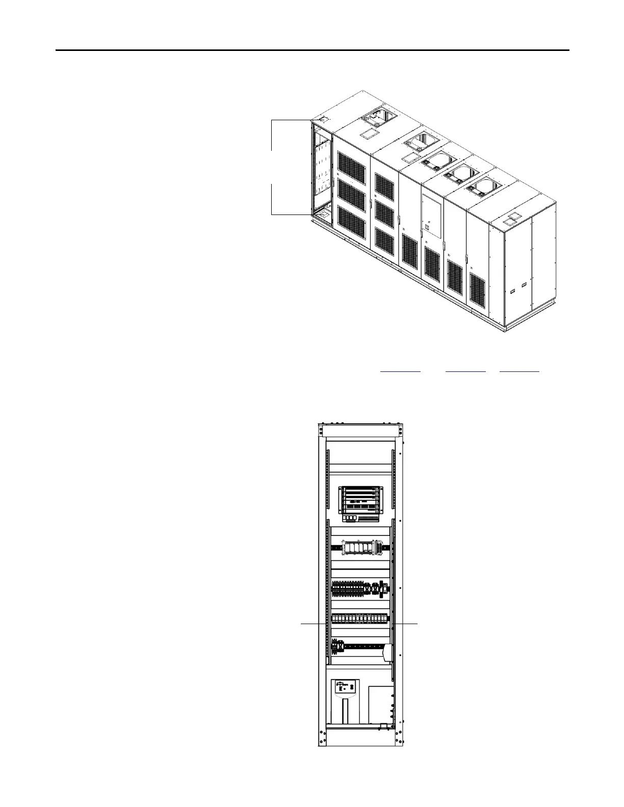
Figure 22 - Control Power Wiring Opening, Type B
The control power wiring terminates to the DTB1 terminal block strip on the
left side of the LV Control cabinet (Figure 23
). See Figure 30 or Figure 31 for
general overview. Refer to Electrical Drawings for actual connection points.
Figure 23 - Terminal Block Strip locations
Cable entrance in
top or bottom front
of LV Control Cabinet
DTB1 Terminal
Block strip
DTB2 Terminal
Block strip

Table of Contents

Other manuals for Allen-Bradley PowerFlex 6000

Questions and Answers:

Question and Answer IconNeed help?

Do you have a question about the Allen-Bradley PowerFlex 6000 and is the answer not in the manual?

Allen-Bradley PowerFlex 6000 Specifications

General IconGeneral
BrandAllen-Bradley
ModelPowerFlex 6000
CategoryDC Drives
LanguageEnglish

Related product manuals