Rockwell Automation Publication 20A-UM001N-EN-P - July 2013 59
Programming and Parameters Chapter 1
UTILITY (file E)
Faults
243
245
247
249
[Fault 1 Code]
[Fault 2 Code]
[Fault 3 Code]
[Fault 4 Code]
A code that represents the fault that tripped the
drive. The codes appears in these parameters in
the order they occur ([Fault 1 Code] = the most
recent fault).
Default:
Min/Max:
Units:
Read Only
0/9999
0/65535
0
214
238
244
246
248
250
[Fault 1 Time]
[Fault 2 Time]
[Fault 3 Time]
[Fault 4 Time]
Default:
Min/Max:
Units:
Read Only
0.0000/429496.7295 Hrs
0.0001 Hrs
242
The time between initial drive power up and the occurrence of the associated trip fault. Can
be compared to [Power Up Marker] for the time from the most recent power up.
[Fault x Time] – [Power Up Marker] = Time difference to the most recent power up. A
negative value indicates fault occurred before most recent power up. A positive value
indicates fault occurred after most recent power up.
To convert this value to the number of days, hours, minutes and seconds, use the following
formulas:
• Fault x Time / 24 hours = (# of days).(remaining time)
• Remaining Time x 24 hours = (# of hours).(remaining time)
• Remaining Time x 60 minutes = (# of minutes).(remaining seconds)
• Remaining Time x 60 seconds = (# of seconds)
• Result = (# of days).(# of hours).(# of minutes).(# of seconds)
Example:
• 1909.2390 Hrs / 1 Day/24 Hrs = 79.551625 Days
• 0.551625 Days x 24 Hrs/Day = 13.239 Hrs
• 0.239 Hrs x 60 Min/Hr = 14.34 Min
• 0.34 Min x 60 Sec/Min = 20.4 Secs
Alarms
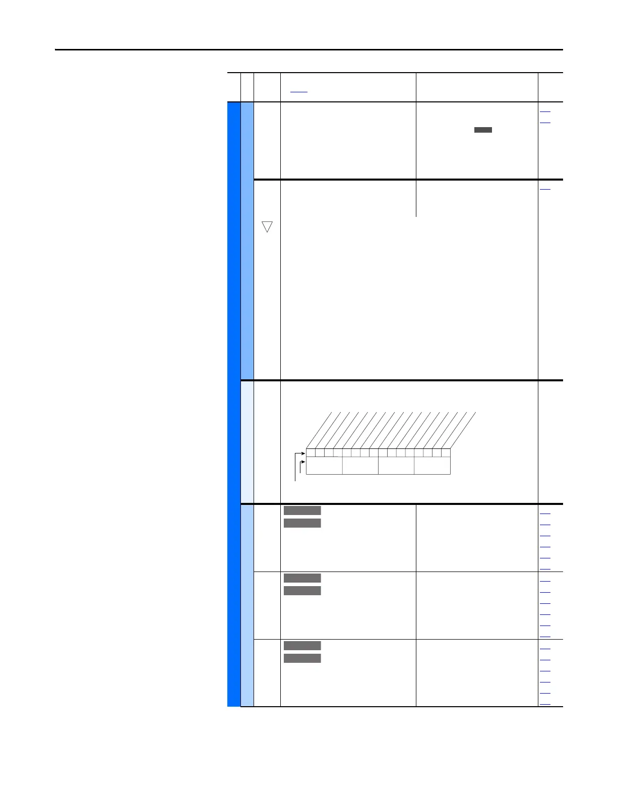
259 [Alarm Config 1]
Enables/disables alarm conditions that initiate an active drive alarm.
Scaled Blocks
476
482
[Scale1 In Value]
[Scale2 In Value]
Displays the value of the signal being sent to
[ScaleX In Value] by using a datalink.
Default:
Min/Max:
Units:
0.0
-3276.8/+3276.7
0.1
090
093
117
126
127
427
477
483
[Scale1 In Hi]
[Scale2 In Hi]
Scales the upper value of [ScaleX In Value].
Default:
Min/Max:
Units:
0.0
-3276.8/+3276.7
0.1
091
094
119
428
460
462
478
484
[Scale1 In Lo]
[Scale2 In Lo]
Scales the lower value of [ScaleX In Value].
Default:
Min/Max:
Units:
0.0
-3276.8/+3276.7
0.1
092
095
120
429
461
463
File E
Group
No.
Parameter Name and Description
See page 14 for symbol descriptions
Values
Related
E C
111111x11101000x
10 01234567891112131415
1=Enabled
0=Disabled
x =Reserved
Bit #
Factory Default Bit Values
Prechrg Actv
UnderVoltage
Power Loss
Str At PwrUp
Anlg in Loss
IntDBRes OH
Drv OL Lvl 1
Drv OL Lvl 2
Decel Inhibt
Waking
(2)
Motor Therm
(1)
In PhaseLoss
(2)
Load Loss
(2)
Ground Warn
(2)
Nibble 1Nibble 2Nibble 3Nibble 4
(1)
Enhanced firmware 1.001 & later.
(2)
Enhanced firmware 2.001 & later.
 Loading...


