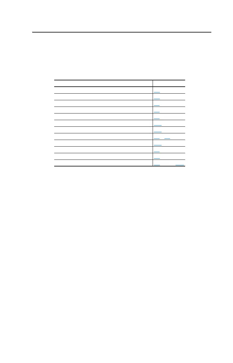
EasyManuals Logo

Allen-Bradley powerflex 700 User Manual

Allen-Bradley powerflex 700
198 pages
To Next Page IconTo Next Page
To Previous Page IconTo Previous Page
Page #5 background imageLoading...
Page #5 background image
Summary of Changes
The information below summarizes the changes to the PowerFlex 700
User Manual, publication 20B-UM001 since the last release.
Manual Updates
Change Page
Bypass Attention statement added P-3
Catalog Number Explanation updated P-4
Mounting section updated 1-2
Shield Termination description updated 1-4
Power Terminal Block Specifications updated 1-9
Recommended Signal Wire table updated 1-15
CE General Notes & Table 1.I updated 1-25
“Flashing, Drive Stopped” Status Indicator updated 2-2 & 4-2
[Dig Out Setpt] description updated 3-58
“Decel Inhibit” Action #3 updated 4-5
Sound Pressure specification added A-2
Motor Starter catalog numbers updated A-8 through A-12

Table of Contents

Other manuals for Allen-Bradley powerflex 700

Questions and Answers:

Question and Answer IconNeed help?

Do you have a question about the Allen-Bradley powerflex 700 and is the answer not in the manual?

Allen-Bradley powerflex 700 Specifications

General IconGeneral
SeriesPowerFlex 700
CategoryAC Drive
Input Voltage200-240V AC, 380-480V AC, 500-600V AC
EnclosureType 1
Control MethodSensorless Vector
CommunicationEtherNet/IP, ControlNet, DeviceNet, PROFIBUS DP, Modbus

Related product manuals