3-42 Programming and Parameters
UTILITY
Diagnostics
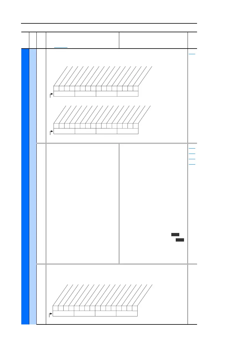
212 [Drive Alarm 2]
Alarm conditions that currently exist in the drive.
Read Only 211
213 [Speed Ref Source]
Displays the source of the speed
reference to the drive.
(1)
Vector firmware 3.001 and later.
Default:
Options: 0
1
2
3-6
7
8
9
10
11-17
18
19
20
21
22
23
24
25
26
27
28
29
Read Only
“PI Output”
“Analog In 1”
“Analog In 2”
“Reserved”
“Pulse In”
“Encoder”
“MOP Level”
“Jog Speed 1”
“Preset Spd1-7”
“DPI Port 1”
“DPI Port 2”
“DPI Port 3”
“DPI Port 4”
“DPI Port 5”
“Reserved”
“Auto Tune”
“Jog Speed 2”
“Scale Block 1”
(1)
“Scale Block 2”
(1)
“Scale Block 3”
(1)
“Scale Block 4”
(1)
090
093
096
101
214 [Start Inhibits]
Displays the inputs currently preventing the drive
from starting.
Read Only
File
Group
No.
Parameter Name & Description
See page 3-2 for symbol descriptions
Values
Related
0000000000000000
10 01234567891112131415
1 =Condition True
0 =Condition False
x =Reserved
Bit #
DigIn CflctA
DigIn CflctB
DigIn CflctC
Bipolr Cflct
MtrTyp Cflct
NP Hz Cflct
MaxFrq Cflct
VHz NegSlope
IR Vlts Rang
FlxAmps Rang
SpdRef Cflct
Ixo Vlt Rang
Sleep Config
TB Ref Cflct
PTC Conflict *
Brk Slipped *
xxx 0xxxxxxxxxxxx
26 161718192021222324252728293031
1 =Condition True
0 =Condition False
x =Reserved
Bit #
TrqPrv Cflct *
* Vector firmware 3.001 & later
Vector
Vector
0000100x100000xx
10 01234567891112131415
1 =Inhibit True
0 =Inhibit False
x =Reserved
Bit #
Fault
Type 2 Alarm
Enable
DC Bus Pchrg
Stop Assertd
Params Reset
Startup Actv
Digital In
DPI Port 1
DPI Port 2
DPI Port 3
DPI Port 4
DPI Port 5
 Loading...


