Programming and Parameters 3-45
UTILITY
Diagnostics
229 [Alarm 1 @ Fault]
Captures and displays [Drive Alarm 1] at the time of
the last fault.
Read Only 211
224
thru
230
230 [Alarm 2 @ Fault]
Captures and displays [Drive Alarm 2] at the time of
the last fault.
Read Only 212
224
thru
230
234
236
[Testpoint 1 Sel]
[Testpoint 2 Sel]
Selects the function whose value is
displayed value in [Testpoint x Data].
These are internal values that are not
accessible through parameters.
See Testpoint Codes and Functions
on
page 4-16 for a listing of available codes
and functions.
Default:
Min/Max:
Units:
499
0/65535
1
235
237
[Testpoint 1 Data]
[Testpoint 2 Data]
The present value of the function
selected in [Testpoint x Sel].
Default:
Min/Max:
Units:
Read Only
0/4294967295
–/+2147483648
1
File
Group
No.
Parameter Name & Description
See page 3-2 for symbol descriptions
Values
Related
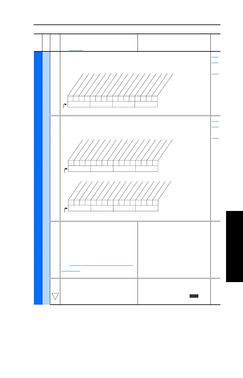
000000x00000000x
10 01234567891112131415
1 =Condition True
0 =Condition False
x =Reserved
Bit #
Prechrg Actv
UnderVoltage
Power Loss
Str At PwrUp
Anlg in Loss
IntDBRes OH
Drv OL Lvl 1
Drv OL Lvl 2
Decel Inhibt
Waking
Motor Therm *
In PhaseLoss *
Load Loss *
Ground Warn *
* Vector firmware 3.001 & later
0000000000000000
10 01234567891112131415
1 =Condition True
0 =Condition False
x =Reserved
Bit #
DigIn CflctA
DigIn CflctB
DigIn CflctC
Bipolr Cflct
MtrTyp Cflct
NP Hz Cflct
MaxFrq Cflct
VHz NegSlope
IR Vlts Rang
FlxAmps Rang
SpdRef Cflct
Ixo Vlt Rang
Sleep Config
TB Ref Cflct
PTC Conflict *
Brk Slipped *
xxx 0xxxxxxxxxxxx
26 161718192021222324252728293031
1 =Condition True
0 =Condition False
x =Reserved
Bit #
TrqPrv Cflct *
* Vector firmware 3.001 & later
32
Vector
 Loading...


