C-6 Connector Descriptions
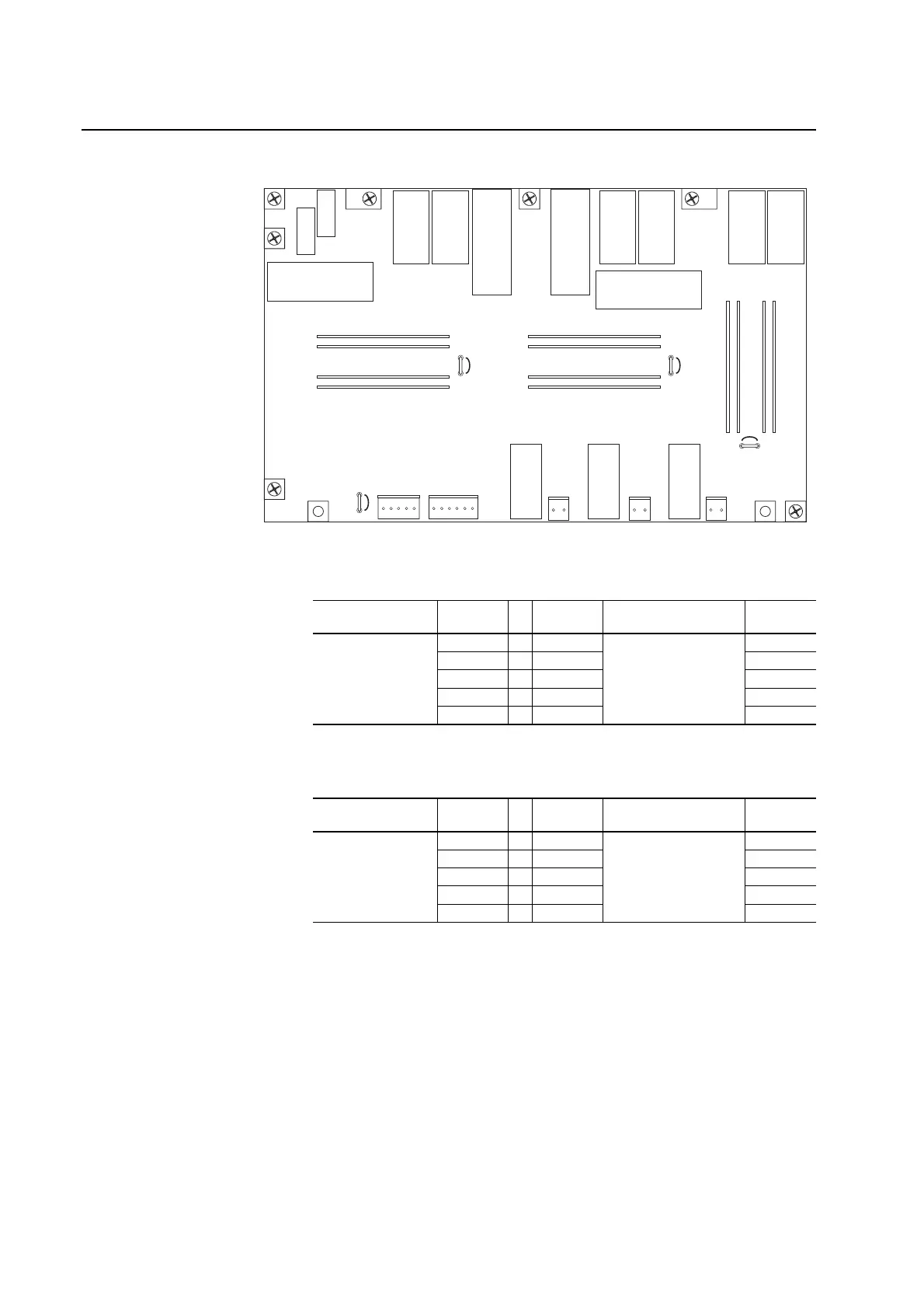
Figure C.3 Rectifier/Precharge Circuit Board Connectors
Table C.G ASIC Board on Power Structure #1 to Rectifier/Precharge Circuit Board on
Power Structure #1 Connections
Table C.H ASIC Board on Power Structure #2 to Rectifier/Precharge Circuit Board on
Power Structure #2 Connections
X13 X6 X10 X11
X12
X9X100
X3
X2
X1
X4
X41
X8
X101
X50
J3
J7
J11
ASIC Board
Connector Pin Number to Pin Number
Rectifier Board
Connector Description
X2 1 . . . 1 X13 SWTS_DRV
2 . . . 2 SWTS_FB
3 . . . 3 W_DTR
4 . . . 4 Mains Fault
5 . . . 5 +24V
ASIC Board
Connector Pin Number to Pin Number
Rectifier Board
Connector Description
X2 1 . . . 1 X13 SWTS_DRV
2 . . . 2 SWTS_FB
3 . . . 3 W_DTR
4 . . . 4 Mains Fault
5 . . . 5 +24V

 Loading...


