Component Test Procedures 2-11
6. Connect the minus (-) probe of the multimeter to the DC- wire. Make
sure these DC+ and DC- connections are insulated from all objects.
7. Connect the High Voltage DC Test Power Supply to these wires.
8. Set the current limit on the High Voltage DC Test Power Supply to less
than or equal to 1A. Energize the Supply and increase its output to the
drive’s nominal DC bus voltage (650V dc for drives with 380-500V ac
input or 775V dc for drives with 600-690V ac input).
!
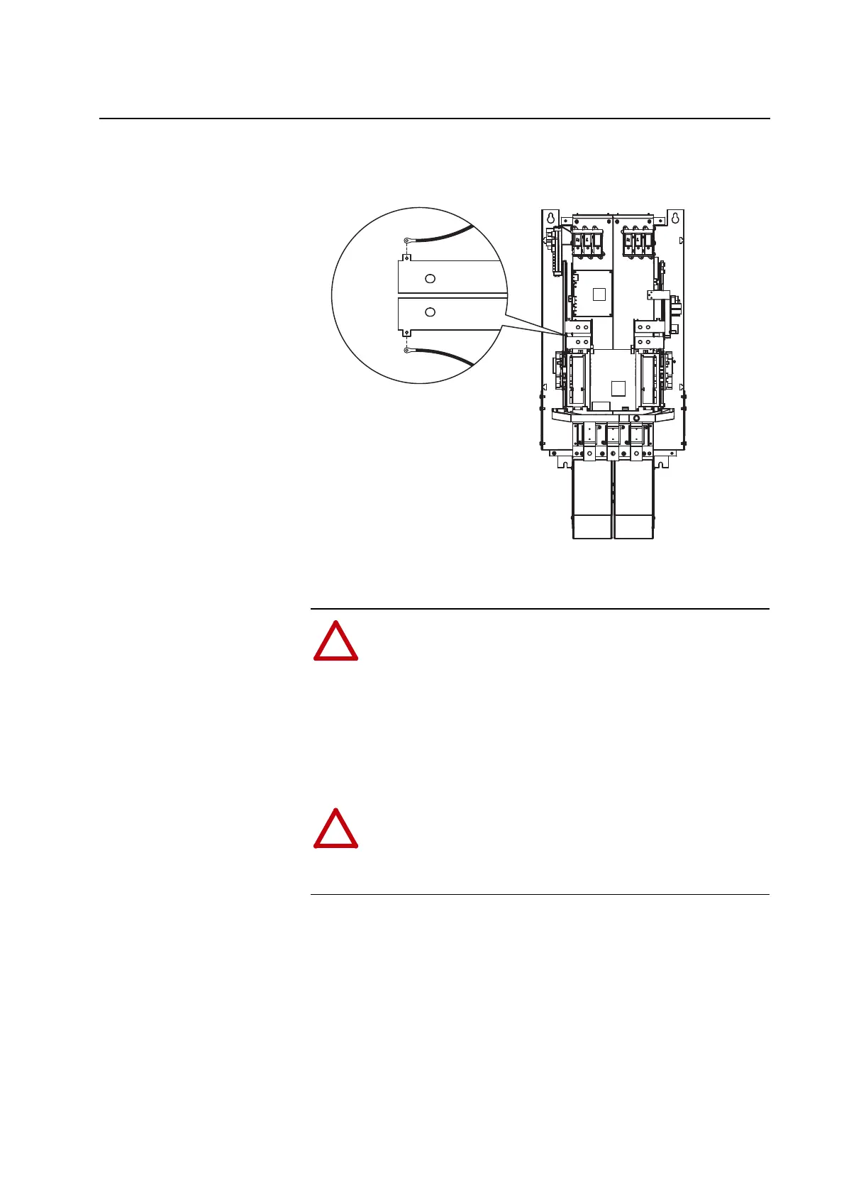
ATTENTION: The sheet metal cover and mounting screws on
the ASIC Boards located on the power structures are energized at
(-) DC bus potential high voltage. Risk of electrical shock,
injury, or death exists if someone comes into contact with the
assembly. Servicing energized equipment can be hazardous.
Severe injury or death can result from electrical shock, burn or
unintended actuation of controlled equipment. Follow Safety
related practices of NFPA 70E, ELECTRICAL SAFETY FOR
EMPLOYEE WORKPLACES. DO NOT work alone on energized
equipment!
!
ATTENTION: Certain pins in connectors X7 and X12 on the
Gate Driver Boards will be energized at DC bus potential high
voltage. Risk of electrical shock,
personal injury or death, property
damage, or economic loss exists if
personnel or equipment comes
into contact with these pins.
DC-
DC+

 Loading...


