3-6 Access Procedures
Frame.
Installation
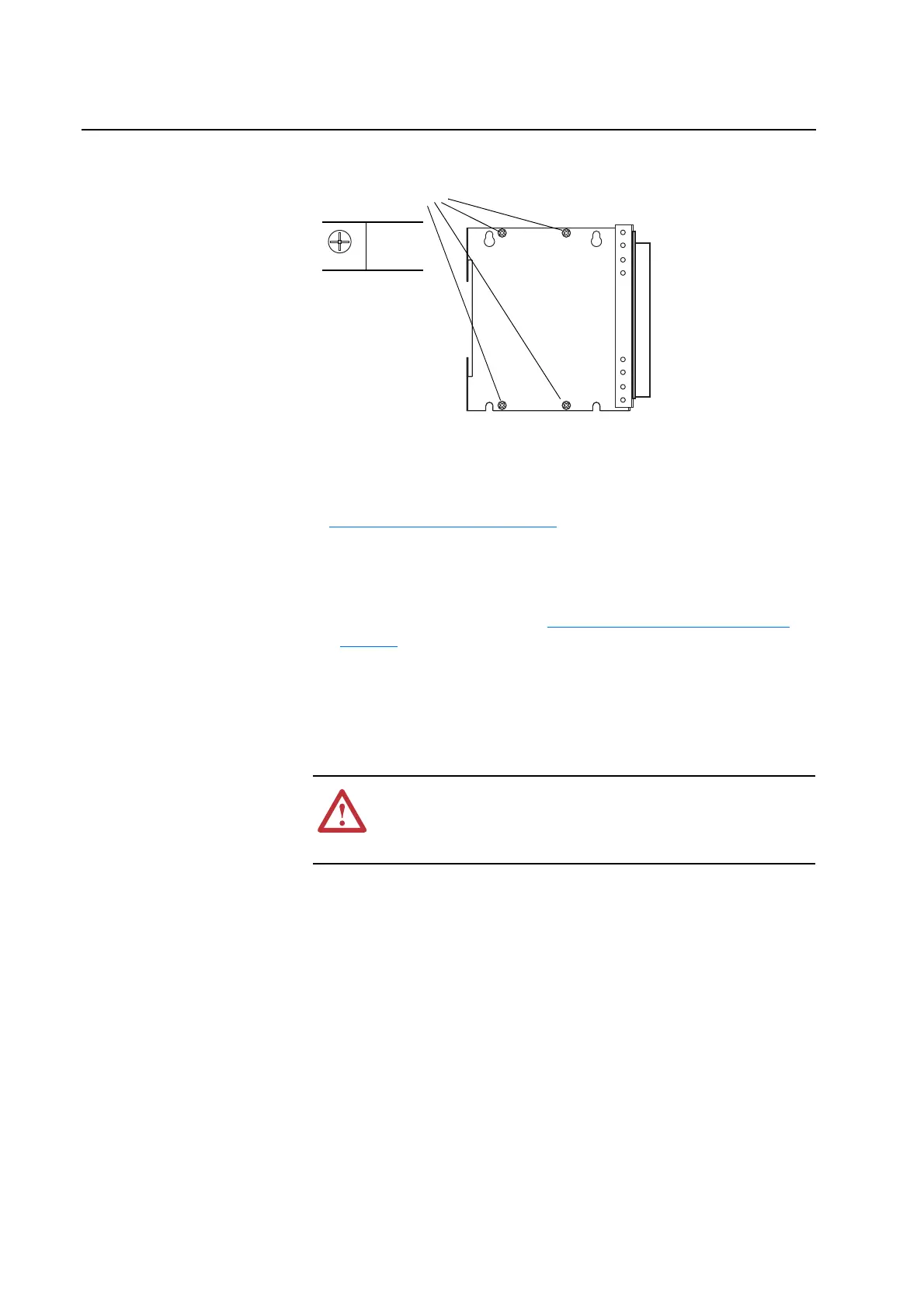
Install the DPI / HIM Assembly in reverse order of removal, while referring
to Torque Specifications on page 3-1
.
Removing the 700S Phase II
Control Assembly
Removal
1. Remove power from the drive (Removing Power from the Drive on
page 3-3).
Important: Before removing connections and wires, mark the connections
and wires to avoid incorrect wiring during assembly.
2. Unplug any fiber optic ControlNet and SynchLink cables from the
Control Assembly.
Important: Minimum inside bend radius for SynchLink and ControlNet
fiber-optic cable is 25.4 mm (1 in.). Any bends with a shorter
inside radius can permanently damage the fiber-optic cable.
Signal attenuation increases with decreased inside bend radii.
3. Unplug any remaining I/O and communications cables from the Control
Assembly and set them aside.
Mounting Screws
P1
0.9 N-m
(8 lb.-in.)
!
ATTENTION: Hazard of permanent eye damage exists when
using optical transmission equipment. This product emits intense
light and invisible radiation. Do not look into fiber-optic ports or
fiber-optic cable connectors.

 Loading...


