EasyManuals Logo

Allen-Bradley PowerFlex 700H User Manual

Allen-Bradley PowerFlex 700H
120 pages
To Next Page IconTo Next Page
To Previous Page IconTo Previous Page
Page #70 background imageLoading...
Page #70 background image
3-34 Access Procedures
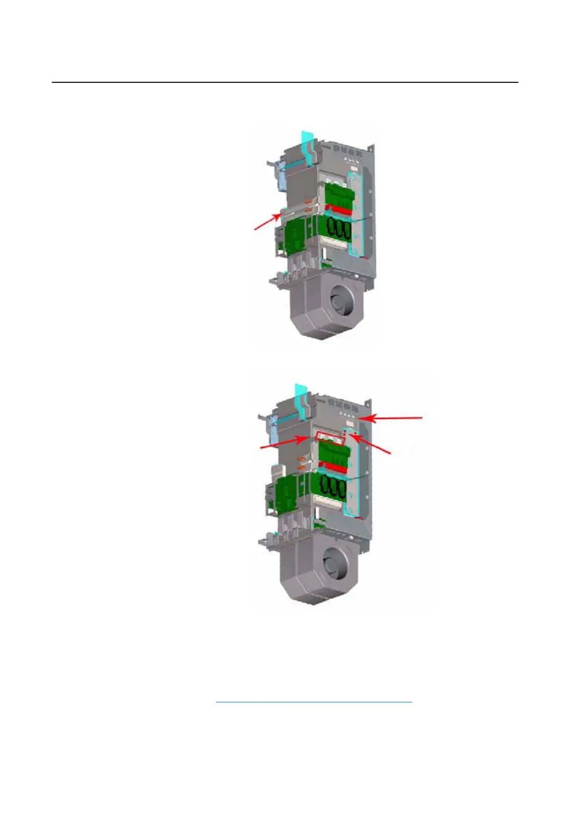
8. Loosen, but do not remove, the screws that secure the Y Bus Bars to the
drive.
9. Remove the balancing resistor wires from bus bars.
10. Disconnect all wiring from the circuit board on the Rectifying Module.
11. Disconnect the cables from the AC input terminals on the Rectifying
Module.
12. Remove the circuit board from the Rectifying Module (refer to
Removing the Rectifying Boards on page 3-29
).
Y Bus Bars
AC Input
Te rm in als
(L1, L2, L3)
Balancing Resistors
Balancing Resistor Wires

Table of Contents

Other manuals for Allen-Bradley PowerFlex 700H

Questions and Answers:

Question and Answer IconNeed help?

Do you have a question about the Allen-Bradley PowerFlex 700H and is the answer not in the manual?

Allen-Bradley PowerFlex 700H Specifications

General IconGeneral
BrandAllen-Bradley
ModelPowerFlex 700H
CategoryController
LanguageEnglish

Related product manuals