3-38 Access Procedures
5. Remove the Inverter Assemblies.
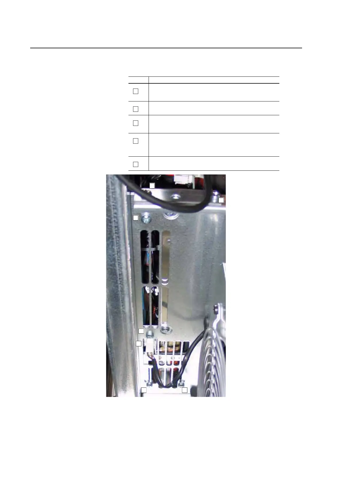
Task Description
Remove the two M5 Pozi-drive screws, which secure the front of the
fan inverter to the drive.
Proper tightening torque for reassembly is 4 N-m (35 lb.-in.).
Disconnect the fan motor cable under the inverter.
Remove the four M5 Pozi-drive screws, which secure the bottom of the
fan inverter to the drive.
Proper tightening torque for reassembly is 4 N-m (35 lb.-in.).
Disconnect the cables at X2, X8 and X3 (on left-hand and center
inverters); and X2 and X8 (on right-hand inverter).
Note: This step is not shown.
Carefully remove the inverters by sliding them out towards the front of
the drive.
A
B
C
D
E
Important: Do not damage the output transformer when removing or
installing the inverter.
Bottom View
of Power Structure
A
A
B
C
C
C C

 Loading...


