Access Procedures 3-39
6. Remove the Inverter from the old Inverter Assembly.
7. Repeat steps 4 - 6 to remove the Fan Inverters from Power Structure 2.
Installation
Install the fan inverters in reverse order of removal, while referring to
Torque Specifications on page 3-1
.
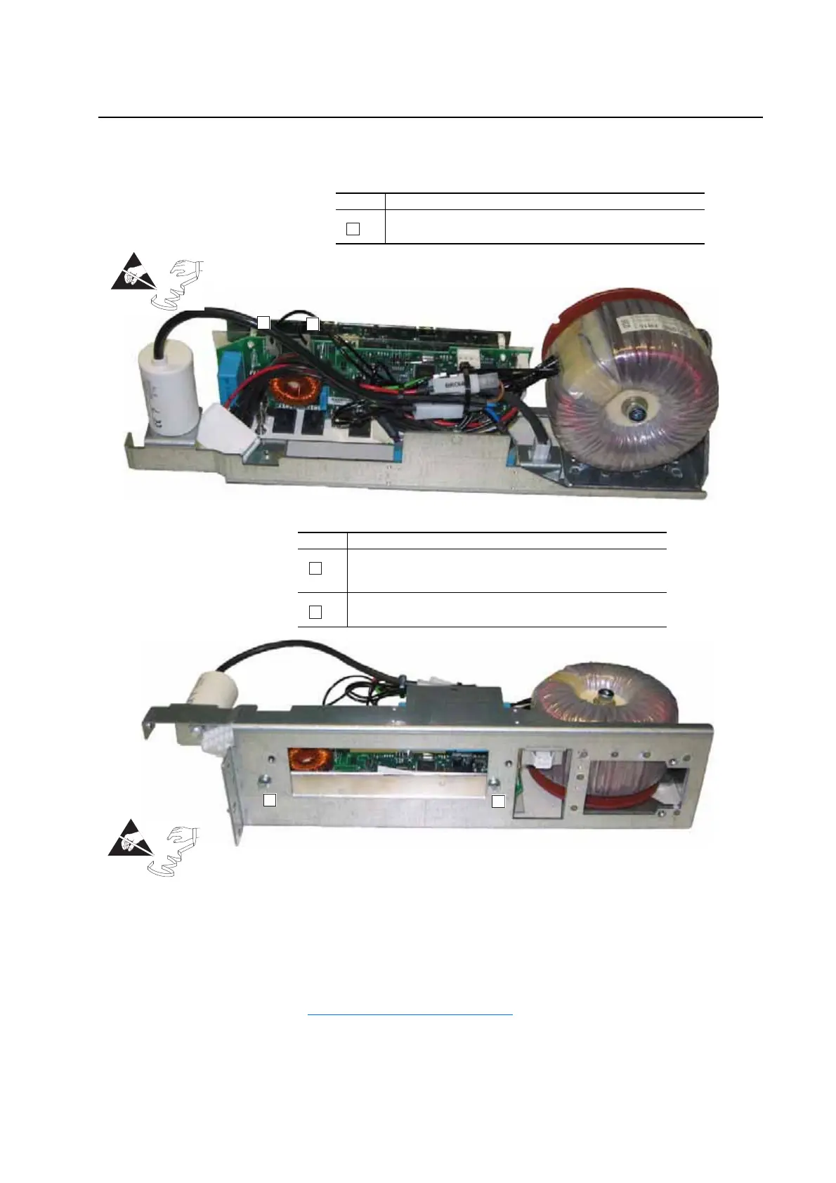
Task Description
Disconnect the cables at connectors X4 (Blue) and X5 (Black).
A
Task Description
Remove two M5 Pozi-drive screws, which secure the inverter board
and its heatsink to the assembly carriage.
Proper tightening torque for reassembly is 4 N-m (35 lb.-in.).
Carefully remove the inverter board and its heatsink from the assembly
carriage.
B
C
Right-hand Inverter Shown
=
A
A
B
B
=

 Loading...


