EasyManuals Logo

Allen-Bradley PowerFlex 700H User Manual

Allen-Bradley PowerFlex 700H
120 pages
To Next Page IconTo Next Page
To Previous Page IconTo Previous Page
Page #76 background imageLoading...
Page #76 background image
3-40 Access Procedures
Removing the DC Bus
Capacitors
Removal
1. Remove power from the drive (Removing Power from the Drive on
page 3-3).
2. Remove the covers from the power structures. Refer to Removing the
Covers from the Power Structures on page 3-15.
3. Remove the power structures from the drive cabinet (Removing the
Power Structures from the Drive Enclosure on page 3-25).
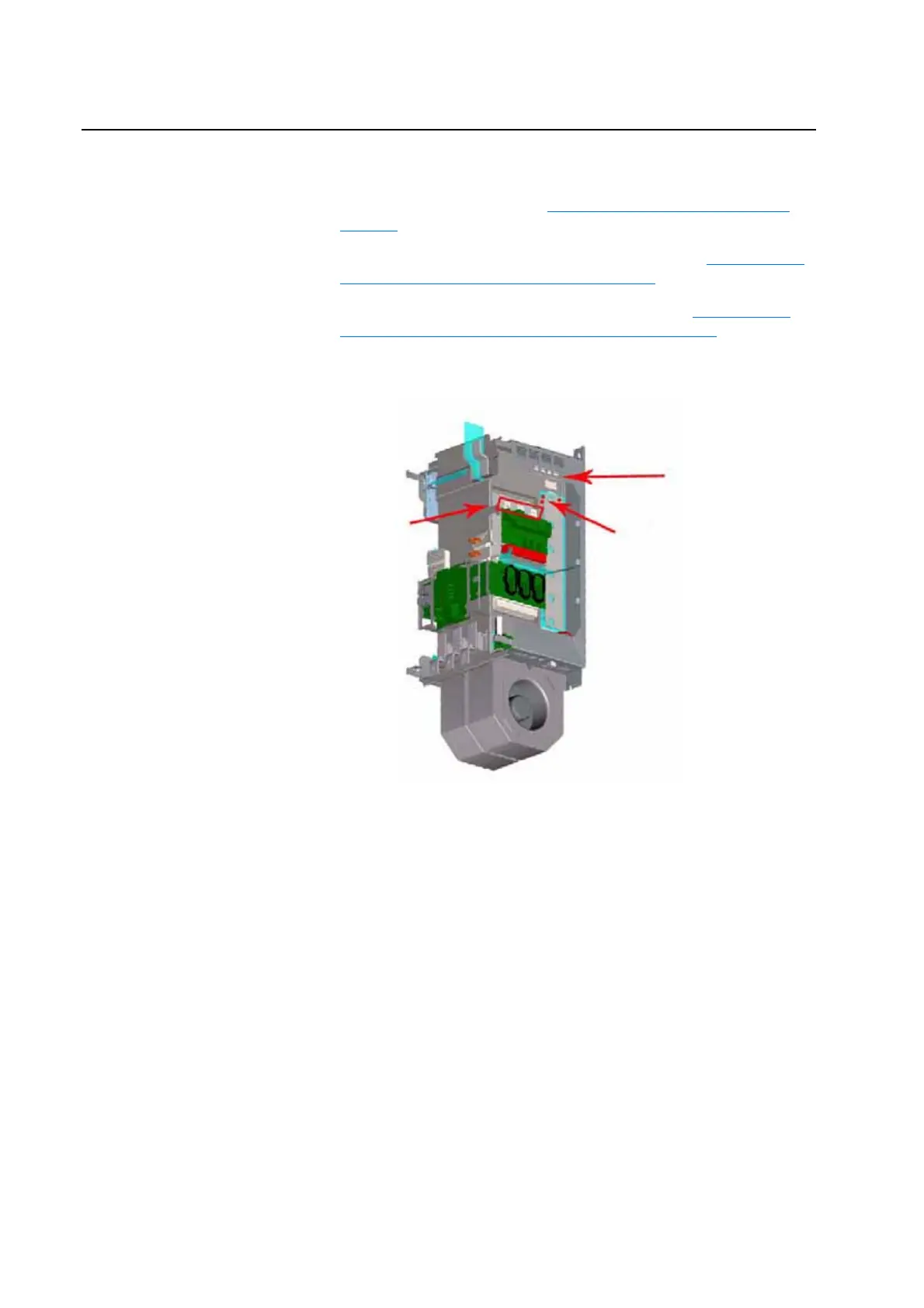
4. For Power Structure 1, remove the balancing resistor wires from bus
bars.
AC Input
Te rm in als
(L1, L2, L3)
Balancing Resistors
Balancing Resistor Wires

Table of Contents

Other manuals for Allen-Bradley PowerFlex 700H

Questions and Answers:

Question and Answer IconNeed help?

Do you have a question about the Allen-Bradley PowerFlex 700H and is the answer not in the manual?

Allen-Bradley PowerFlex 700H Specifications

General IconGeneral
BrandAllen-Bradley
ModelPowerFlex 700H
CategoryController
LanguageEnglish

Related product manuals