Access Procedures 3-41
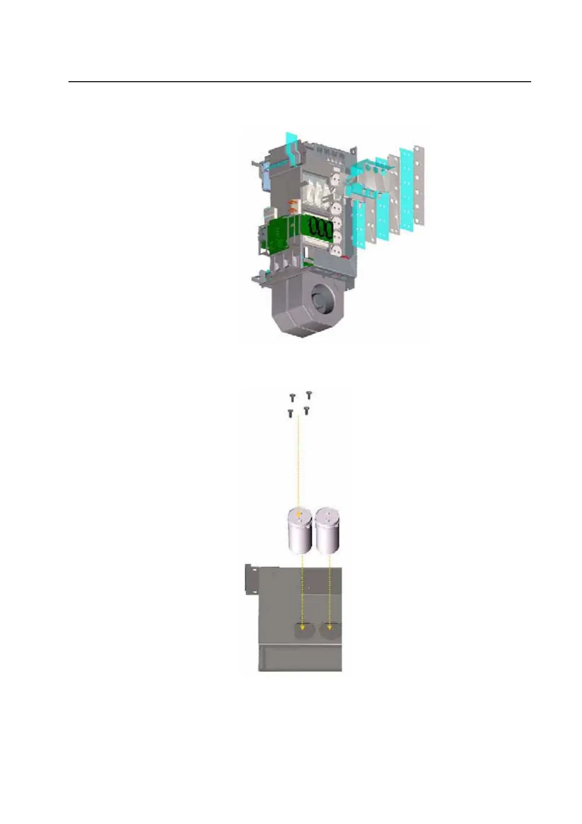
5. Remove the screws that secure DC Bus Bars to right side of power
structure, and remove the DC Bus Bars.
6. Remove the four (4) screws that secure the capacitor to the power
structure, and remove the capacitor.
7. Repeat steps 4 - 6 to remove the DC Bus Capacitors from Power
Structure 2.

 Loading...


