56 Rockwell Automation Publication 750-PM001N-EN-P - February 2017
Chapter 3 Drive Port 0 Parameters
File
Group
No. Display Name
Full Name
Description
Values
Read-Write
Data Type
MOTOR CONTROL
Volts per Hertz
60 Start Acc Boost
Start/Acceleration Boost
The voltage boost level for starting and acceleration when a “VHz” mode is selected,
according to P35 [Motor Ctrl Mode]. Refer to diagram for P524 [Overspeed Limit].
Units:
Default:
Min/Max:
V AC
Based on Drive Rating
0.00 / Based on Drive Rating and Voltage
Class
RW Real
61 Run Boost
Run Boost
The boost level for steady state and deceleration when a “VHz” mode is selected,
according to P35 [Motor Ctrl Mode]. Refer to diagram for P524 [Overspeed Limit].
Units:
Default:
Min/Max:
V AC
Based on Drive Rating
0.00 / Based on Drive Rating and Voltage
Class
RW Real
62 Break Voltage
Break Voltage
The voltage the drive will output at P63 [Break Frequency] when a “VHz” mode is
selected, according to P35 [Motor Ctrl Mode]. Refer to diagram for P524 [Overspeed
Limit].
Units:
Default:
Min/Max:
V AC
Based on Drive Rating and Voltage Class
0.00 / P25 [Motor NP Volts] x 1.5
RW Real
63 Break Frequency
Break Frequency
The frequency the drive will output at P62 [Break Voltage] when a “VHz” mode is
selected, according to P35 [Motor Ctrl Mode]. Refer to diagram for P524 [Overspeed
Limit].
Units:
Default:
Min/Max:
Hz
P27 [Motor NP Hertz] x 0.25
0.00 / P27 [Motor NP Hertz]
RW Real
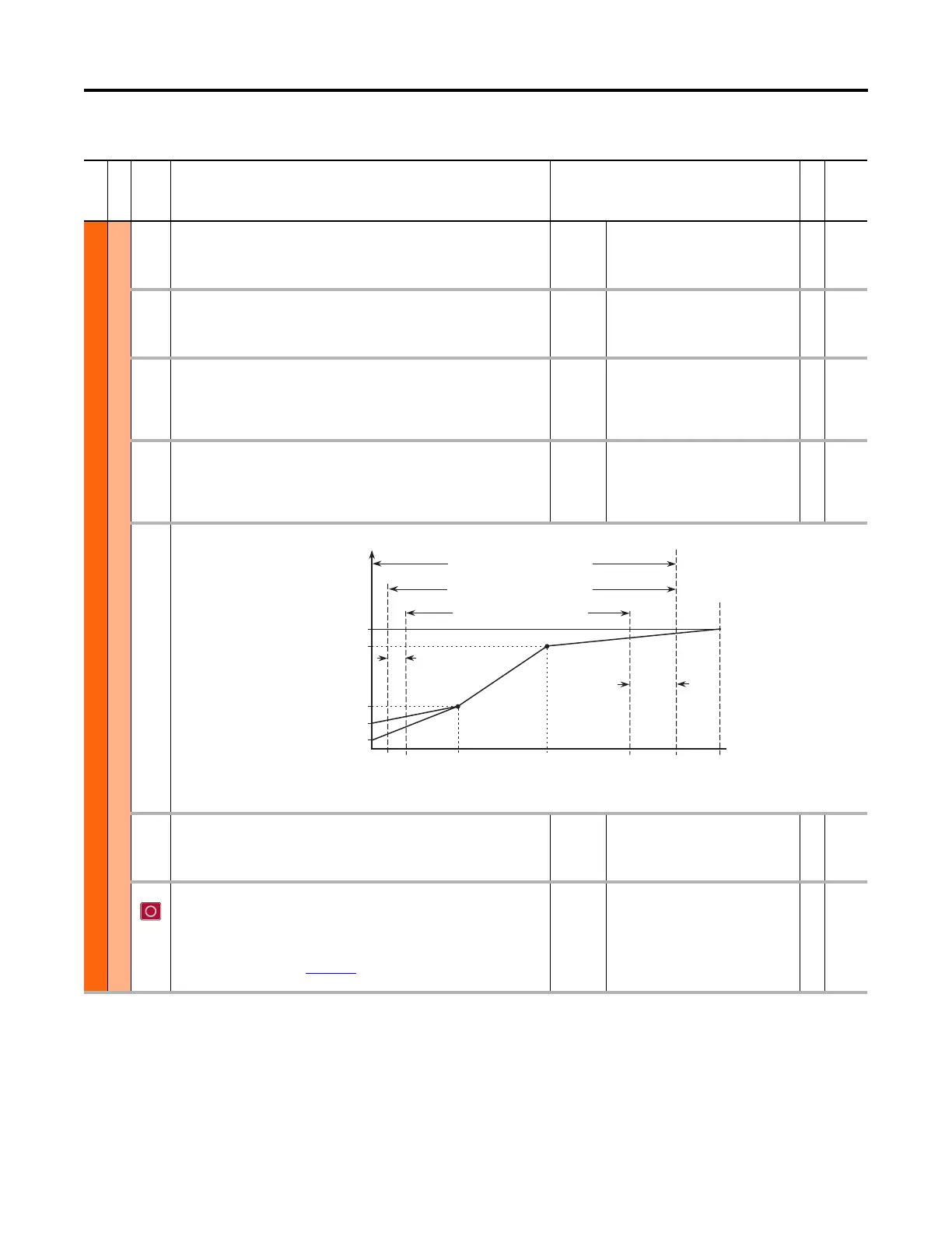
This diagram (with P65 set to Custom V/Hz) depicts the Voltage to Frequency ratio when using the Induction VHz (0) motor control mode.
64 SVC Boost Filter
SVC Boost Filter
The voltage boost filter time constant when a “SVC” mode is selected, according to P35
[Motor Ctrl Mode].
Units:
Default:
Min/Max:
Secs
0.1000
0.0001 / 1000.0000
RW Real
65 VHz Curve
VHz Curve
Selects either a predefined curve (for example Fan/Pump), or a custom curve when a
“VHz” mode is selected, according to P35 [Motor Ctrl Mode]. Refer to diagram for P524
[Overspeed Limit]. See Motor Control Modes in the PowerFlex 750-Series AC Drives
Reference Manual, publication 750-RM002
, for more information on the Fan/Pump
option.
Default:
Options:
0 – Custom V/Hz
0 – Custom V/Hz
1 – Fan/Pump
RW 32-bit
Integer
Frequency
Voltage
P524
[Overspeed
Limit]
Frequency Trim due to
Speed Control Mode
P36 [Max Volts]
P25 [Motor Volts]
P61 [Run]
P62 [Break Volts]
P60 [Start Boost]
Allowable Output Frequency Range -
Normal Operation
Allowable Speed Reference Range
Allowable Output Frequency Range -
Bus Regulation or Current Limit
P37
[Max
Freq]
P27
[Motor Hz]
0
P63
[Break
Frequency]
Max
Speed
P520/P521
[FWD/REV]
Min
Speed
P522/P523
[FWD/REV]
Output
Freq Limit
 Loading...


