Rockwell Automation Publication 750-PM001N-EN-P - February 2017 79
Drive Port 0 Parameters Chapter 3
File
Group
No. Display Name
Full Name
Description
Values
Read-Write
Data Type
FEEDBACK & I/O
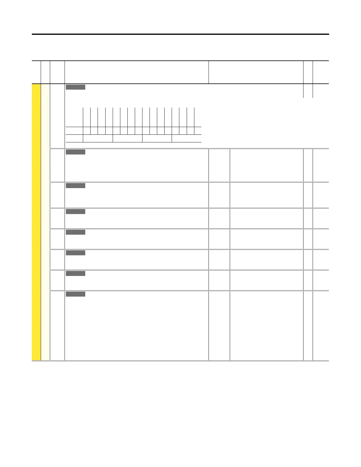
R0 Predict Main
285 RO PredMaint Sts
Relay Output Predictive Maintenance Status
RO 16-bit
Integer
Status of relay 0 predictive maintenance. When the condition of the bit = 1, the predicted relay life has elapsed.
286 RO0 Load Type
Relay Output 0 Load Type
Sets the type of load that will be applied to the relay. Must be properly set for the
Predictive Maintenance function to predict the relay life.
Default:
Options:
1 = “DC Inductive”
0 = “DC Resistive”
1 = “DC Inductive”
2 = “AC Resistive”
3 = “AC Inductive”
RW 32-bit
Integer
287 RO0 Load Amps
Relay Output 0 Load Amps
Load current that will be applied to the relay contacts. Must be properly set for the
Predictive Maintenance function to approximate the relay life.
Units:
Default:
Min/Max:
Amps
2.000
0.000 / 2.000
RW Real
288 RO0 TotalLife
Relay Output 0 Total Life
Total life cycles of the relay based on programmed load type and amps.
Units:
Default:
Min/Max:
Cycl
0
0 / 2147483647
RO 32-bit
Integer
289 RO0 ElapsedLife
Relay Output 0 Elapsed Life
Non-resettable, total accumulated cycles of the relay.
Units:
Default:
Min/Max:
Cycl
0
0 / 2147483647
RO 32-bit
Integer
290 RO0 RemainLife
Relay Output 0 Remaining Life
The difference between the Total Life and the Elapsed Life.
Units:
Default:
Min/Max:
Cycl
0
–/+2147483647
RO 32-bit
Integer
291 RO0 LifeEvntLvl
Relay Output 0 Life Event Level
Sets the percentage of relay life cycles before action is taken.
Units:
Default:
Min/Max:
%
80.000
0.000 / 100.000
RW Real
292 RO0 LifeEvntActn
Relay Output 0 Life Event Action
Sets the action that will be taken when the percentage of relay life cycles has been
reached.
“Ignore” (0) – No action is taken.
“Alarm” (1) – Type 1 alarm indicated.
“Flt Minor” (2) – Minor fault indicated. If running, drive continues to run.
Enable with P950 [Minor Flt Cfg]. If not enabled, acts like a major fault.
“FltCoastStop” (3) – Major fault indicated. Coast to Stop.
“Flt RampStop” (4) – Major fault indicated. Ramp to Stop.
“Flt CL Stop” (5) – Major fault indicated. Current Limit Stop.
Default:
Options:
1 = “Alarm”
0 = “Ignore”
1 = “Alarm”
2 = “Flt Minor”
3 = “FltCoastStop”
4 = “Flt RampStop”
5 = “Flt CL Stop”
RW 32-bit
Integer
Options
Master
Reserved
Reserved
Reserved
Reserved
Reserved
Reserved
Reserved
Reserved
Reserved
Reserved
Reserved
Reserved
Reserved
Reserved
Relay Out 0
Default0000000000000000
Bit 1514131211109876543210
0 = Condition False
1 = Condition True
 Loading...


