Rockwell Automation Publication MOTION-RM003I-EN-P - February 2018 225
The Velocity Threshold attribute defines a minimum absolute velocity. If the
magnitude of the Velocity Feedback signal is less than this value, the Velocity
Threshold status bit is set. If the axis is configured for Frequency Control, the
Velocity Feedback signal is derived from the Velocity Reference signal.
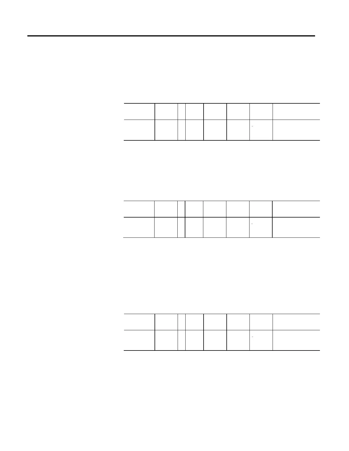
Velocity Lock Tolerance
Usage Access T Data
Type
Default Min Max Semantics of Values
Optional - PV Set/SSV
REAL 1
FD
0
Velocity Units
The Velocity Lock Tolerance attribute establishes a window around the unlimited
velocity reference signal. When the Velocity Feedback signal is within this window
the Velocity Lock status bit is set. When Velocity Feedback signals falls outside
this window, the Velocity Lock status bit is cleared.
Velocity Standstill Window
Usage Access T Data
Type
Default Min Max Semantics of Values
Required - ED Set/SSV
REAL 1
FD
0
Velocity Units
The Velocity Standstill Window attribute establishes a window around zero
speed. When the Velocity Feedback signal is within this window the Velocity
Standstill status bit is set. When Velocity Feedback signal falls outside this
window, the Velocity Standstill status bit is cleared. If the axis is configured for
Frequency Control, the Velocity Feedback signal is derived from the Velocity
Reference signal.
Velocity Limit - Positive
Usage Access T Data
Type
Default Min Max Semantics of Values
Optional - FPV Set/SSV
REAL 0
FD
0
Velocity Units
The Velocity Limit - Positive attribute defines the most positive velocity reference
value into the velocity summing junction. If the signal entering the velocity limiter
exceeds this velocity limit value, the device responds by clamping the velocity
reference to this limit and sets the Velocity Limit status bit.

 Loading...


