Interpret the Attribute Tables
Rockwell Automation Publication MOTION-RM003I-EN-P - February 2018 91
Attribute Unit Applicable Units Semantics of Values
Filter Frequency Units Hz Hertz
Counts
Fundamental control unit for distance.
For example, feedback counts or planner counts.
See also
CIP Data Types on page 91
CIP Axis Attributes on page 185
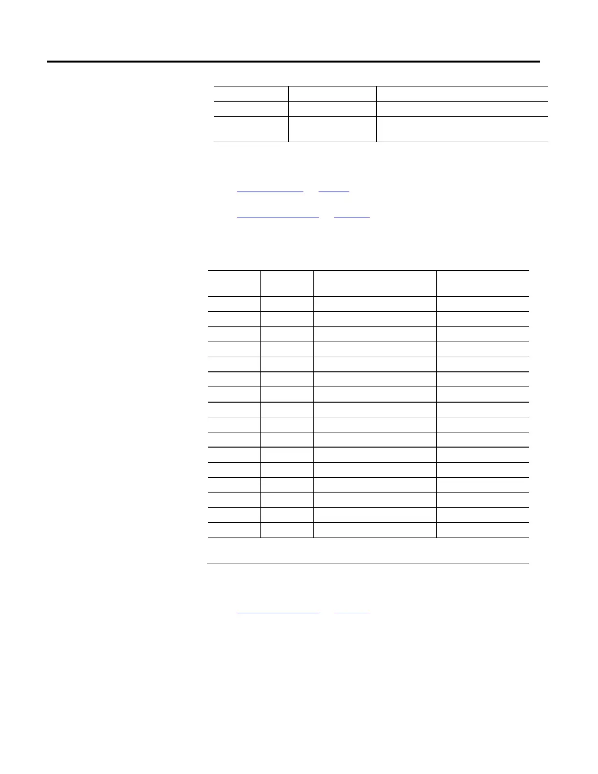
This table provides descriptions of the CIP Data Types related to the CIP Motion
Control Axis.
Data Type
Name
Data Type Code
(hex)
Description Range
BOOL* C1 Boolean 0 = FALSE; 1 = TRUE
SINT C2 Short Integer -128 SINT 127
INT C3 Integer -32768 INT 32767
DINT C4 Double Integer -2
31
DINT (2
31
– 1)
LINT C5 Long Integer -2
63
LINT (2
63
– 1)
USINT C6 Unsigned Short Integer 0 USINT 255
UINT C7 Unsigned Integer 0 UINT 65536
UDINT C8 Unsigned Double Integer 0 UDINT (2
32
– 1)
ULINT C9 Unsigned Long Integer 0 ULINT (2
64
– 1)
REAL CA Single Precision Float See IEEE 754
LREAL CB Double Precision Float See IEEE 754
BYTE D1 bit string – 8-bits N/A
WORD D2 bit string – 16-bits N/A
DWORD D3 bit string – 32-bits N/A
LWORD D4 bit string – 64-bits N/A
SHORT STRING DA {length, 1-byte characters[n]} N/A
* BOOL data type is defined by CIP standard to be an 8-bit unsigned integer with enumeration of 0 for False and 1 for
True.
See also
CIP Axis Attributes on page 185
The variations in Control Mode and Control Method result in a set of basic
Device Function Codes that help organize the many attributes of the Motion
Control Axis. Device Function Codes are designated by using a letter identifier or
a combination that you can use to determine what attributes are required for
implementation of a given CIP Motion device. The list of Device Function Codes
is as follows:

 Loading...


