Rockwell Automation Publication MOTION-RM003I-EN-P - February 2018 249
The Registration 1 Negative Edge Time attribute is the CST time stamp on the
falling edge of the Registration Input 1.
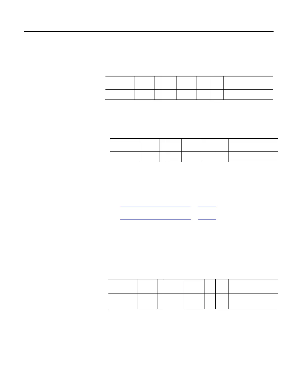
Registration 2 Positive Edge Time
Usage Access T Data
Type
Default Min Max Semantics of Values
Required - E Get/GSV T DINT - - - CST Time in Microseconds
The Registration 2 Positive Edge Time attribute is the CST Time stamp on the
rising edge of the Registration Input 2.
Registration 2 Negative Edge Time
Usage Access T Data
Type
Default Min Max Semantics of Values
Required - E Get/GSV T DINT - - - CST Time in Microseconds
The Registration 2 Negative Edge Time attribute is the CST Time stamp on the
falling edge of the Registration Input 2.
See also
Motion Control Signal Attributes on page 330
Motion Control Status Attributes on page 341
These attribute tables contain attributes associated with the drive. Drive attributes
reside both on the controller and on the drive.
These are the attributes that provide to general purpose analog and digital I/O
associated with the Motion Control Axis.
Digital Inputs
Usage Access T Data Type Default Min Max Semantics of Values
Optional - BD Get/GSV T DWORD - - - Vendor Specific Bit Map
The Digital Inputs attribute is a 32-bit word with whose bits can be assigned by
the vendor to general purpose digital inputs.
Drive General Purpose I/O
Attributes

 Loading...


