Rockwell Automation Publication MOTION-RM003I-EN-P - February 2018 229
Acceleration Feedforward Command
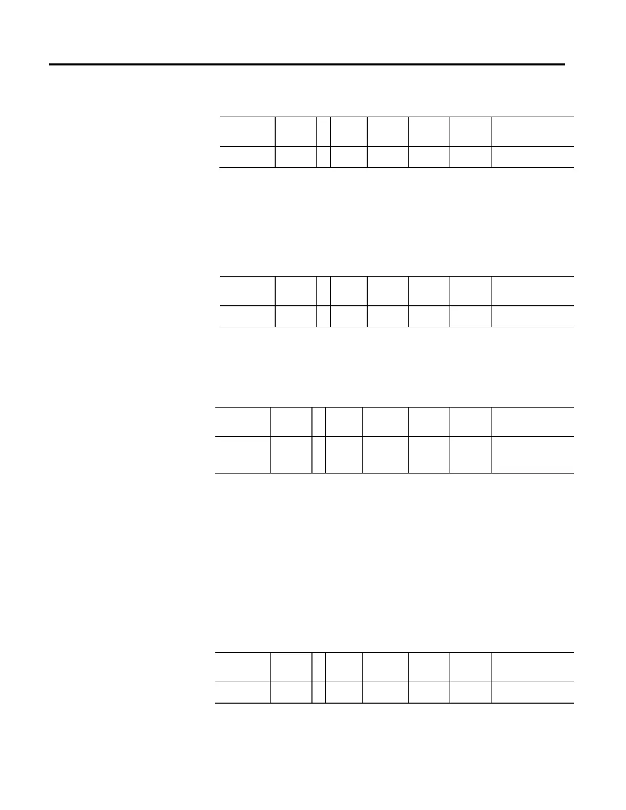
Usage Access T Data
Type
Default Min Max Semantics of Values
Required - PV Get/GSV T REAL - - - Accel Units
The Acceleration Feedforward Command attribute is a signal that represents a
scaled version of the command acceleration profile. This signal is the Acceleration
Fine Command signal scaled by Acceleration Feedforward Gain and applied to the
output of the velocity loop.
Velocity Reference
Usage Access T Data
Type
Default Min Max Semantics of Values
Required - FPV Get/GSV T REAL - - - Velocity Units
Command velocity reference into velocity loop summing junction, or in the case
of Frequency Control, the signal that is scaled to become the Frequency Reference.
Velocity Feedback
Usage Access T Data
Type
Default Min Max Semantics of Values
Required - All Get/GSV T REAL - - - Velocity Units
Actual velocity of the axis applied to the velocity summing junction, if applicable,
based on Control Mode selection. In most cases the Velocity Feedback signal is
derived directly from the feedback device specified by the Feedback Mode
selection. If the axis is configured for Feedback Only mode, Velocity Feedback
represents the actual velocity of the feedback device. If the axis is configured for
Frequency Control, the Velocity Feedback signal is derived from the Velocity
Reference signal. If configured for Sensorless Velocity Loop operation, i.e.
Feedback Mode set to No Feedback, Velocity Feedback is estimated by the
sensorless control algorithm.
Velocity Error
Usage Access T Data
Type
Default Min Max Semantics of Values
Required - PV Get/GSV T REAL - - - Velocity Units
Error between the velocity reference and velocity feedback value that is the output
of the velocity loop summing junction.

 Loading...


