Rockwell Automation Publication MOTION-RM003I-EN-P - February 2018 305
active device Control Modes it is assumed that logical channel, Feedback 1, is
attached directly to the motor while Feedback 2 is attached to the load side of the
mechanical transmission. Commutation signals for a PM motor are always derived
from the Feedback 1. The Feedback Configuration attribute is used by the
controller to set the Feedback Mode attribute that is sent to the drive device.
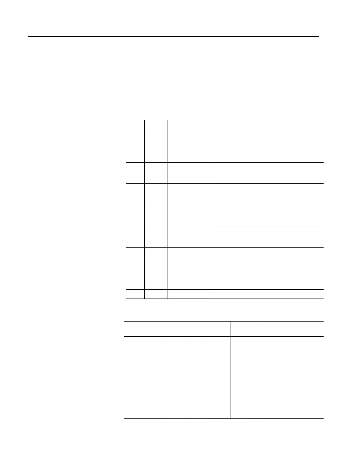
The following table provides descriptions of the Feedback Configuration
enumerations:
Bit Usage Name Description
0 R/S No Feedback
No Feedback is selected when sensorless open loop or closed loop
control is desired. When performing open loop control, no feedback
signal is required. In closed loop control, the required feedback
signal is estimated by a sensorless control algorithm based on
motor phase voltage and current signals.
1 R/N Master Feedback
Master Feedback assigns an uncommitted feedback channel to this
device axis instance to serve as a master feedback source when the
device is configured for No Control mode
2 R/C Motor Feedback
When Motor Feedback is selected, then commutation, acceleration,
velocity, and position feedback signals are all derived from motor
mounted Feedback 1
3 O/C Load Feedback
When Load Feedback is selected, then motor-mounted Feedback 1
is only used for PM motor commutation while load-side Feedback 2
is used for position, velocity, and acceleration.
4 O/P Dual Feedback
When Dual Feedback is selected, then motor mounted Feedback 1 is
used for commutation, acceleration, and velocity, and load-side
Feedback 2 is used strictly for position.
5...7 - Reserved -
8 O/P Dual Integrator Feedback
Dual Integral Feedback means that motor-mounted Feedback 1 is
used for commutation, acceleration, velocity, and position
proportional control, and load-side Feedback 2 is used only for
integral position control. This optimizes the stiffness of the control
loop at low frequency.
9...15 - Reserved -
Feedback Mode
Usage Access Data
Type
Default Min Max Semantics of Values
Required - All
Derived from
Feedback
Configuration
Get/SSV
*
USINT 0 0 15 Bits 0-3: Feedback Mode
Enumeration
0 = No Feedback
1 = Master Feedback
2 = Motor Feedback
3 = Load Feedback
4 = Dual Feedback
5...7 = Reserved
8...15 = Vendor Specific
8 = Dual Int Feedback
4...7 = Reserved

 Loading...


