Rockwell Automation Publication MOTION-RM003I-EN-P - February 2018 427
Guard Status Bit Descriptions
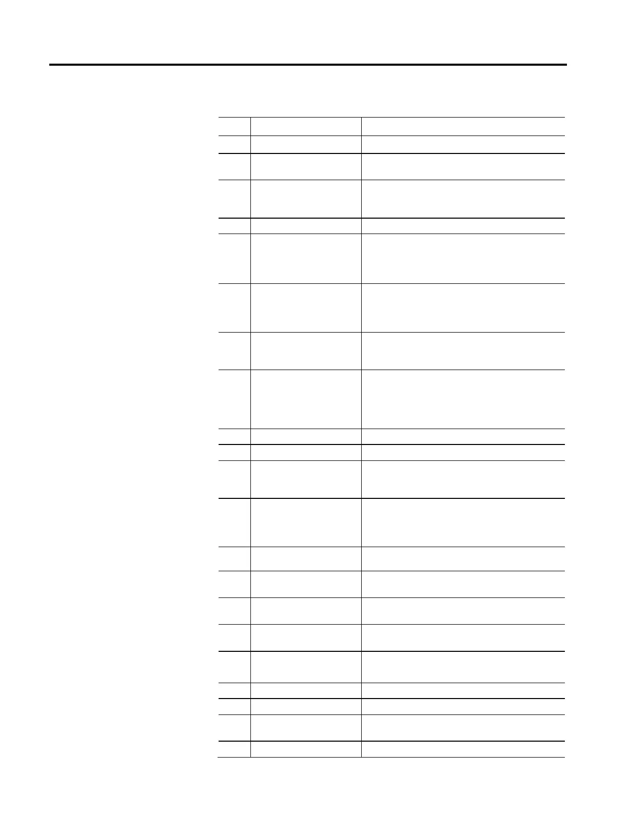
Bit Name Description
0 Guard OK Indicates if the drive is free of any Guard Fault conditions.
1 Guard Config Locked
Indicates that configuration data for the drive safety core has been
locked and cannot be modified.
2 Guard Gate Drive Output
Indicates the state of the Gate Drive (MP OUT) circuit used to disable
the drive power structure.
3 Guard Stop Input Indicates the current state of the Safe Stop input.
4 Guard Stop Request
Indicates if a safe stop operation has been requested. The safe stop
request can be initiated by the Safe Stop Input or in response to a
Safety Fault. The bit is only cleared by a successful safety reset.
5 Guard Stop In Progress
Indicates if the Safe Stop (SS) function of the safety core is in
progress. This bit is set when the Safe Stop input transitions from on
to off and clears at the end of the stop delay or when a safety fault
occurs.
6 Guard Stop Decel
Indicates if the Safe Stop (SS) function of the safety core is actively
decelerating the axis. This bit is set after the monitoring delay expires
and clears at the end of the stop delay or when a fault occurs.
7 Guard Stop Standstill
Indicates if the Safe Stop (SS) function of the safety core is in the safe
stopped mode, for example, when it has successfully stopped the axis
and is performing zero speed monitoring. This bit is set after the stop
delay expires and clears when a fault occurs.
8 Guard Stop Output Indicates the current state of the Safe Stop output.
9 Guard Limited Speed Input Indicates the current state of the Safe Limited Speed (SLS) input.
10 Guard Limited Speed Request
Indicates if a safe speed operation has been requested. The safe stop
request can be initiated by the Safe Limited Speed input. The bit is
only cleared by a successful safety reset.
11
Guard Limited Speed Monitor In
Progress
Indicates if the Safe Speed (SLS/SSM) monitoring function of the
safety core is actively checking speed. This bit is set when the Safe
Limited Speed input transitions from on to off and the associated
monitoring delay has expired.
12 Guard Limited Speed Output Indicates the current state of the Safe Limited Speed (SLS) output.
13
Guard Max Speed Monitor In
Progress
Indicates if the Safe Max Speed (SMS) monitoring function of the
safety core is in progress.
14
Guard Max Accel Monitor In Progress
Indicates if the Safe Max Accel (SMA) monitoring function of the
safety core is in progress.
15 Guard Direction Monitor In Progress
Indicates if the Safe Direction Monitoring (SDM) function of the safety
core is in progress.
16 Guard Door Control Lock
Indicates if the Door Control Output is being commanded to the
Locked state.
17 Guard Door Control Output Indicates the current state of the Safe Door Control output.
18 Guard Door Monitor Input Indicates the current state of the Door Monitor (DM) input.
19 Guard Door Monitor In Progress
Indicates if the Safe Door Monitoring (DM) function of the safety core
is in progress.
20 Guard Lock Monitor Input Indicates the current state of the Safe Lock Monitoring input.

 Loading...


