Rockwell Automation Publication MOTION-RM003I-EN-P - February 2018 441
slip, a Brake Slip exception is generated along with a Brake Malfunction start
inhibit.
The sequencing of the torque and brake "prove" tests are described in detail by the
Mechanical Brake Engage Delay and Mechanical Brake Release Delay attributes.
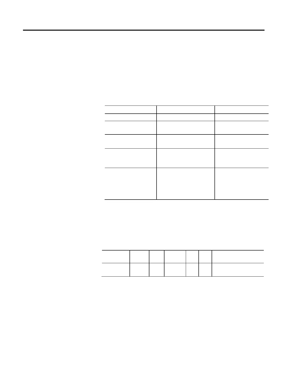
The Proving feature includes a number of optional Sub-Features, many of which
depend on support of other Proving feature attributes. The following table defines
these attribute dependencies.
Proving Sub-Feature Controlling Attributes Attribute Prerequisites
Torque Prove Torque Prove Current Proving Configuration
Brake Test Brake Test Torque
Brake Slip Tolerance
Proving Configuration
Brake Prove Brake Prove Ramp Time
Brake Slip Tolerance
Proving Configuration
Auto Sag Auto Sag Configuration
Auto Sag Slip Increment
Proving Configuration
Brake Prove Ramp Time
Brake Slip Tolerance
Auto Sag Start Auto Sag Start Proving Configuration
Brake Prove Ramp Time
Brake Slip Tolerance
Auto Sag Configuration
Auto Sag Slip Tolerance
Proving tests are performed when enabling or disabling the drive axis. During
these state transitions a series of operations are performed by the drive to ensure
the proper function of the motor (Torque Proving) and the brake (Brake
Proving).
Torque Prove Current
Usage Access Data
Type
Default Min Max Semantics of Values
Optional - D Set/SSV REAL 0
FD
0 10
3
% Motor Rated
This attribute sets the percent of motor rated torque applied to the motor by the
Torque Prove test as part of the Torque Proving function executed in the Starting
state. The Torque Prove test applies current to the motor to "prove" that current is
properly flowing through each of the motor phases before releasing the brake.

 Loading...


