466 Rockwell Automation Publication MOTION-RM003I-EN-P - February 2018
• 0 = Ignore (All)
• 1 = Alarm (All)
• 2 = Fault Status Only (B, D)
• 3 = Stop Planner (D)
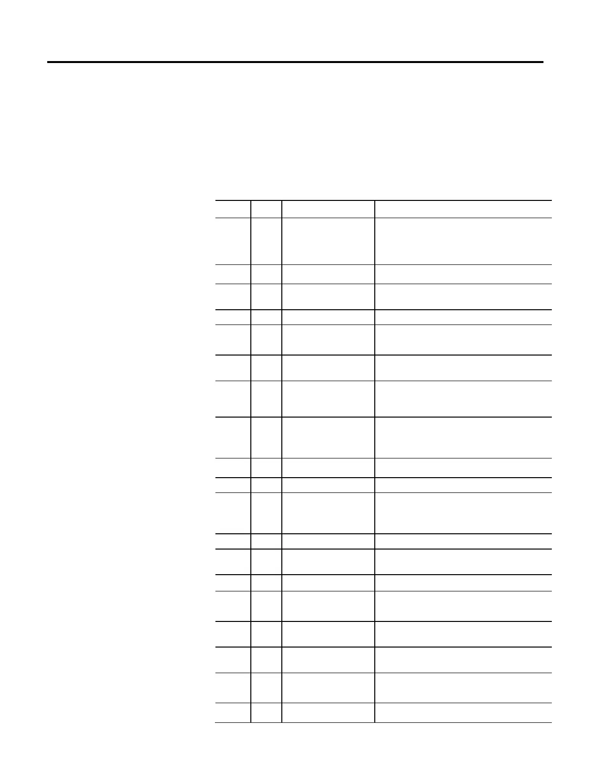
Rockwell Automation Specific Exception Table
Bit Rule Exception Name Description
0 - -- Reserved --
This bit cannot be used since the Alarm Codes and Fault Code
are defined by the associated exception bit number and an
Alarm Code or Fault Code of 0 means no alarm or fault
condition is present.
1 D Commutation Startup Failure The self-sensing commutation startup algorithm failed.
2 D Motor Voltage Mismatch
The motor voltage is incompatible with the applied drive
voltage.
3 - -- Reserved --
4 E Feedback Filter Noise
Excessive levels of noise have been detected by the digital
feedback filter.
5 E Feedback Battery Loss
The battery charge level is too low and encoder power has
been removed possibly resulting in loss of absolute position.
6 E Feedback Battery Low
The battery charge level is too low but encoder power has not
yet been removed. This is intended as a warning that if
encoder power is lost absolute feedback position could be lost.
7 E
Feedback Incremental Count
Error
The periodic check of the incremental encoder position against
the absolute encoder position or Hall edges indicates they are
out of tolerance.
8 - -- Reserved --
9 - -- Reserved --
10 ALL
Control Module
Overtemperature FL
Kinetix: The control module temperature has exceeded its
limit. Rhino: The temperature sensor on the Main Control
Board detected excessive heat.
11
--Reserved--
12 BD
Converter Pre-Charge Overload
FL
Converter estimates that the pre-charge circuit has exceeded
its factory limit due to excessive power cycling.
13
--Reserved--
14 BD
Excessive Current Feedback
Offset
Current in one or more phases has been lost or remains below
a preset level.
15 BD
Regenerative Power Supply
Failure
The hardware Regeneration OK input was deactivated while
the drive was enabled.
16 D PWM Frequency Reduced
Carrier Frequency foldback due to excessive Junction
Temperature.
17 D Current Limit Reduced
Current Limit reduced due to excessive Junction Temperature
or due to Overload Protection.
18 D Torque Prove Failure Actual feedback indicates error in torque proving.

 Loading...


