Module Configuration Attributes
476 Rockwell Automation Publication MOTION-RM003I-EN-P - February 2018
• "Shared DC" specifies that this drive is sharing DC bus power generated by
another Shared AC/DC or Shared DC/DC CIP Motion drive, or external
CIP Motion Converter.
• "Shared DC - Non CIP Converter" specifies that this drive is receiving DC
bus power generated by an external AC/DC converter that is not CIP
Motion compliant and distributing its DC bus power to other CIP Motion
drives. A drive configured for "Shared DC - Non CIP Converter" is
responsible for communicating the state of the external converter to the
control system as if the external converter were integrated with the drive.
Specifically, this communication includes the Bus Up and DC Bus Unload
status bits reflecting the current state of associated external converter.
• "Shared DC/DC" specifies that the converter associated with this CIP
Motion device supplies and shares DC bus power with other Shared DC
devices. DC/DC converters may convert input DC bus power from a
Shared AC/DC converter to a different DC bus output voltage level to
supply one or more Shared DC drives. It may also simply distribute DC bus
power from a Shared AC/DC converter to multiple Shared DC drives
without any conversion. A Shared DC/DC converter has a unique
capability in that it can be both a bus master for a bus group and a bus slave
in a different bus group.
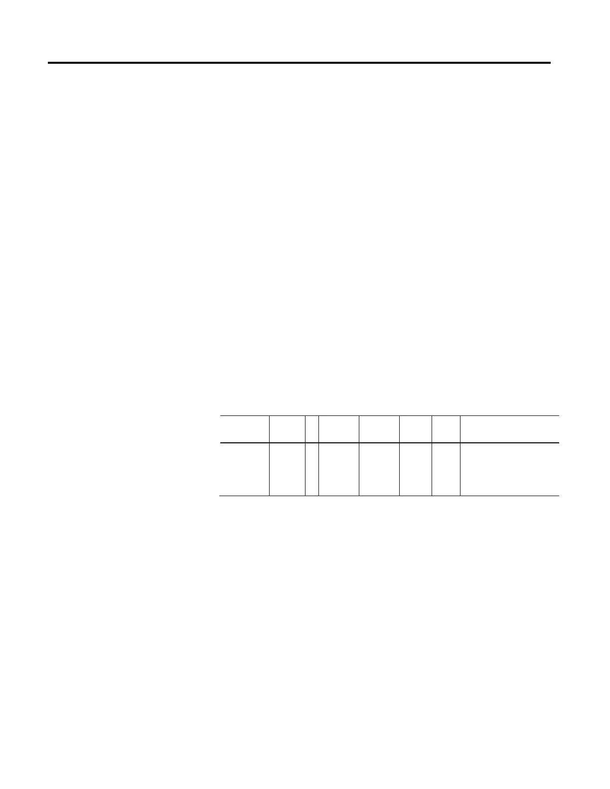
Bus Voltage Select
Usage Access T Data Type Default Min Max Semantics of Values
Optional - D Set
USINT 0 - - Enumeration:
0 = High (115V, 230V, 460V)
1 = Low (100V, 200V, 400V)
2 - 255 = (reserved)
This value indicates the expected bus voltage level of the drive application. High
bus voltage selection is usually associated with drive running on the North
American power grid, when operating in Europe a Low Bus Voltage selection
would be appropriate. This parameter can be used to compensate for these
different bus voltage levels in the current loop.

 Loading...


