Rockwell Automation Publication 1783-IN012A-EN-P - July 2017 7
Stratix 8000 and 8300 Ethernet Managed Switches
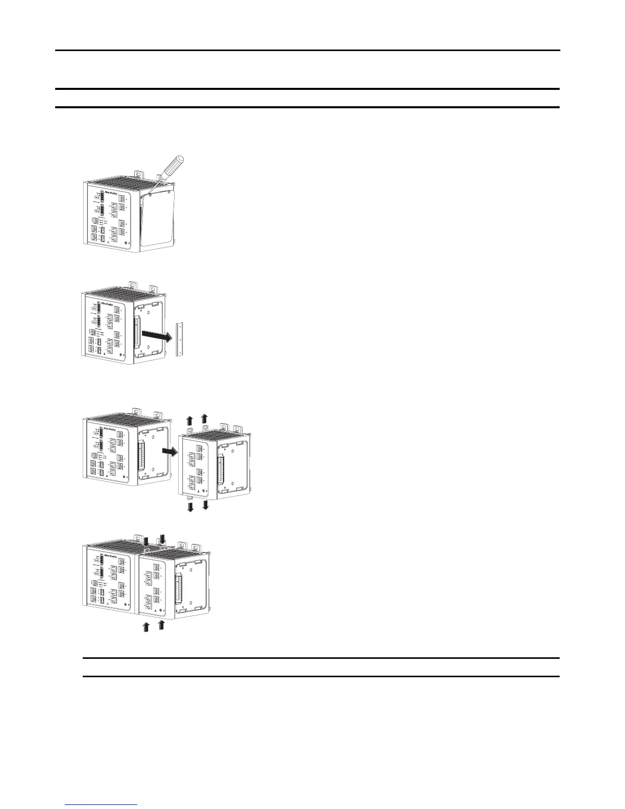
To connect the expansion modules to the switch, follow these steps.
1. Remove the right side panel by firmly grasping both sides of it in the middle and pulling it outward.
If necessary, use a screwdriver to pry open the side panel.
2. Remove the protective EMI-connector cover from the side panel.
3. Push the upper module latches up and the lower module latches down. Then slide the switch and module together.
The expansion module is shown with the side panel removed. Do not remove this panel unless you plan to install another module.
4. Push the upper and lower module latches in to secure the module to the switch.
5. If you are installing a second module, repeat this procedure, but secure the second module to the right side of the first module.
IMPORTANT You must add expansion modules to the base unit before you apply power to the switch. Remove power from the switch when reconfiguring it.
IMPORTANT You cannot install an expansion module to the right of the 1783-MX08F or 1783-MX08S fiber expansion module.
31779-M
31787-M
31780-M
31781-M

 Loading...


