10 Rockwell Automation Publication 1783-IN012A-EN-P - July 2017
Stratix 8000 and 8300 Ethernet Managed Switches
6. Insert the ground screw into the ground-screw opening on the front panel.
7. Use a ratcheting torque screwdriver to tighten the ground screw and ring terminal lug to the switch front panel to 0.96 N•m (8.5 lb•in).
8. Attach the other end of the ground wire to a grounded bare-metal surface, such as a ground bus, or a grounded DIN rail.
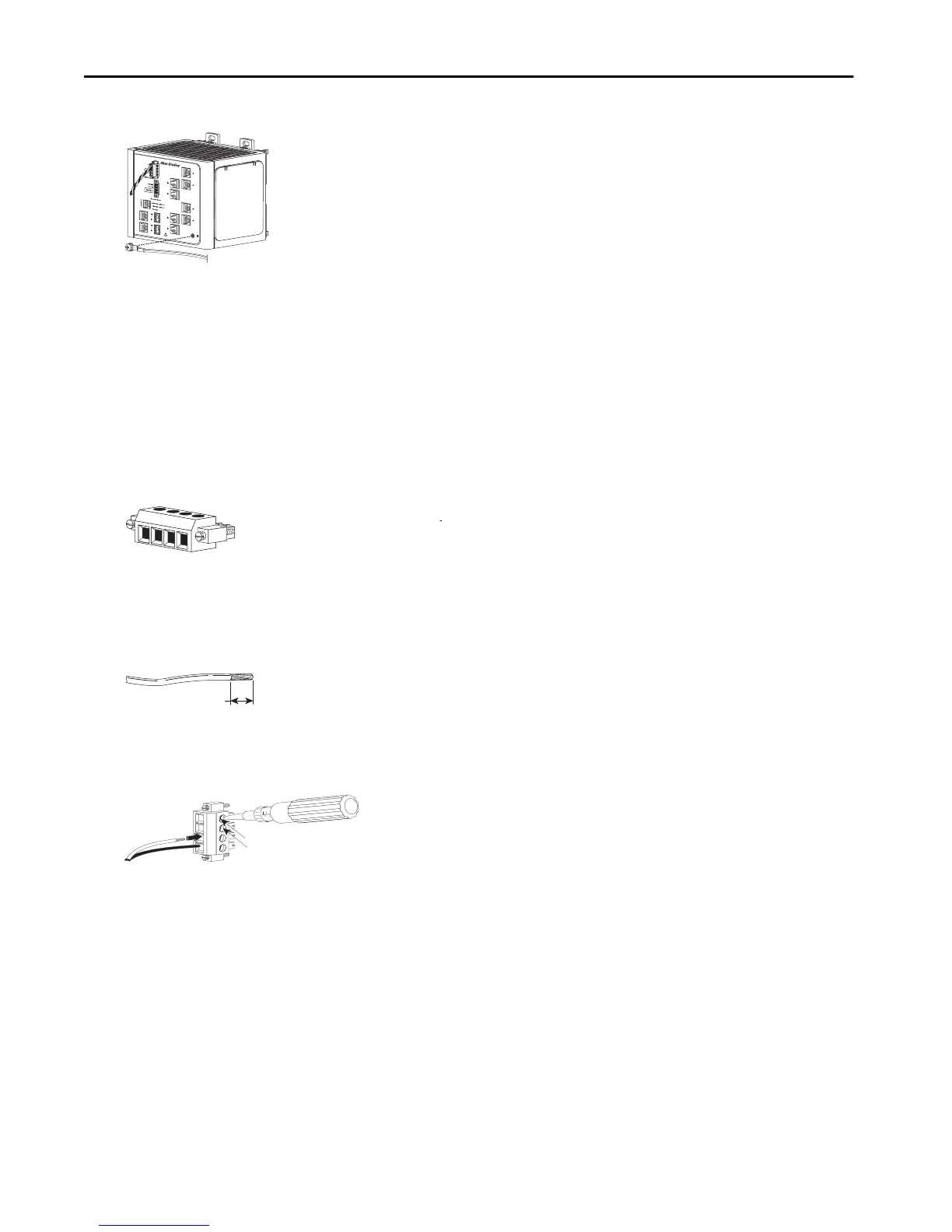
Wire the Power Source for the Switch
Follow these steps to wire DC power to the switch.
1. Locate the power and alarm relay connector and identify the positive and return DC power connections.
The positive DC power connection is labeled V, and the negative DC power connection is the adjacent connection labeled RT.
Connections labeled A are used for the alarm relay connectors.
2. Measure a length of 0.82…0.52 mm
2
(18…20 AWG) copper wire long enough to connect to the DC power source.
3. Using an 18-gauge wire-stripping tool, strip each of the two wires to 6.3 mm (0.25 in.) ± 0.5 mm (0.02 in.).
Do not strip more than 6.8 mm (0.27 in.) of insulation from the wire. Stripping more than the recommended amount of wire can leave
exposed wire from the connector after installation.
4. Insert the exposed part of the positive wire into the connection labeled V and the exposed part of the return wire into the connection
labeled RT.
Make sure that you cannot see any wire lead. Only wire with insulation can extend from the connector.
5. Use a ratcheting-torque screwdriver to torque the power and relay connector captive screws above the installed wire leads to 0.23 N•m
(2.0 lb•in).
6. Connect the other end of the positive wire (the one connected to V) to the positive terminal on the DC power source, and connect the
other end of the return wire (the one connected to RT) to the return terminal on the DC power source.
You can use a second power source to provide redundant power. The alarm relays on the switch can be used to warn you if one of the power
supplies fails. The switch operates properly with only one power source connected at either Pwr A or Pwr B.
7. If you are installing the switch and are using a second power source, repeat these with a second power and relay connector.
VRTA A
31791-M
RT
A
V
A
31783-M
31784-M
6.8 mm (0.27 in.)
VRTA A
31785-M
V
RT

 Loading...


