Motion Event Instructions
272 Rockwell Automation Publication MOTION-RM002H-EN-P-February 2018
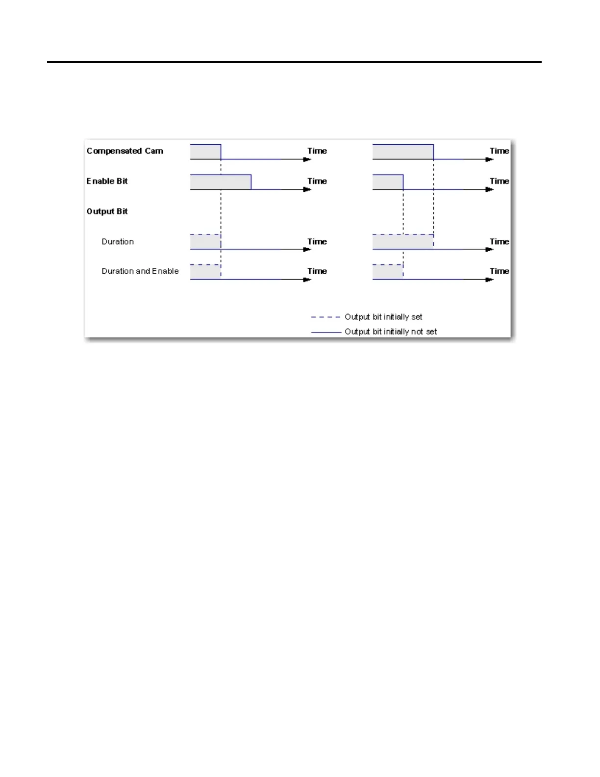
The following diagram shows the effect of the selected unlatch type on the output
bit for different compensated cam and enable bit combinations as function of
time.
Left and Right Cam Positions
The Left and Right cam positions define the range of an Output Cam element. If
the latch or unlatch type is set to "Position" or "Position and Enable" with the
enable bit active, the left and right cam positions specify the latch or unlatch
position of the output bit.
Duration
If the unlatch type is set to "Duration" or "Duration and Enable" with the enable
bit active, the cam duration specifies the time between the latching and the
unlatching of the output bit.
Enable Type
Depending on the selected enable type, the enable bit is an element of either the
input, inverted input, output, or inverted output.
Output Cam Array Checks
The following output cam array checks are used with the MAOC instruction:
• If you select an output bit less than 0 or greater than 31, the Output Cam
element is not considered and the user is warned with an instruction error
Illegal Output Cam.
• If you select a latch type less than 0 or greater than 3, a value of "Inactive" is
used and the user is warned with an instruction error Illegal Output Cam.
 Loading...


