Motion Configuration Instructions
Rockwell Automation Publication MOTION-RM002H-EN-P-February 2018 331
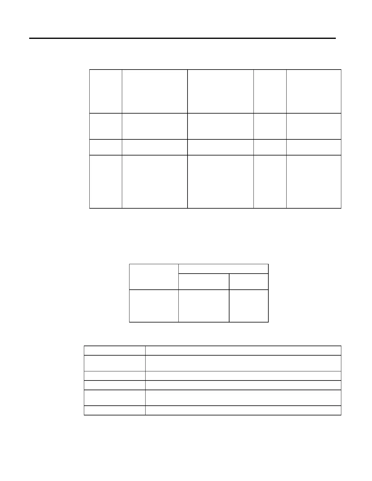
Ladder Diagram and Structured Text
Operand Type
CompactLogix 5380,
CompactLogix 5480,
ControlLogix 5580, Compact
GuardLogix 5380, and
GuardLogix 5580 controllers
Type
CompactLogix 5370,
ControlLogix 5570, Compact
GuardLogix 5370, and
GuardLogix 5570 controllers
Format Description
Axis AXIS_CIP_DRIVE
AXIS_CIP_DRIVE
AXIS_SERVO
AXIS_SERVO_DRIVE
Tag Name of the axis to perform
operation on
Motion Control MOTION_INSTRUCTION MOTION_INSTRUCTION Tag Structure used to access
instruction status parameters.
Diagnostic test DINT DINT Immediate Selects the specific test for the
motion module to run:
0 = motor/encoder hookup
test
1 = encoder hookup test
2 = encoder marker test
3=commutation test
See Structured Text Syntax for more information on the syntax of expressions
within structured text.
For the operands that require you to select from available options, enter your
selection as:
This Operand Has These Options Which You
Enter as Text Or Enter as a
Number
DiagnosticTest motor_encoder
encoder
marker
commutation
0
1
2
3
MOTION_INSTRUCTION Structure
Mnemonic Description
.EN (Enable) Bit 31 It is set when the rung makes a false-to-true transition and remains set until the servo message transaction is
completed and the rung goes false.
.DN (Done) Bit 29 It is set after the hookup test apply process has been successfully executed.
.ER (Error) Bit 28 It is set to indicate that the instruction detected an error, such as if you specified an unconfigured axis.
.IP (In Process) Bit 26 It is set on positive rung transition and cleared after the diagnostic test process is complete, or terminated by a
stop command, shutdown, or a servo fault.
.PC (Process Complete)Bit 27 It is set after the diagnostic test process has been successfully completed.
 Loading...


