Multi-Axis Coordinated Motion Instructions
Rockwell Automation Publication MOTION-RM002H-EN-P-February 2018 383
Dynamics Data
Profile
• Trapezoidal31 (0): When the value is set to 0 the profile setting takes
precedence over the acceleration Jerk and deceleration Jerk value (values are
defaulted to 0%), as a result the velocity profile is always trapezoidal. See
Profile topic in MCLM for more details.
• S Curve (1): When the value is set to 1 the acceleration and deceleration
jerk values are taken into account. The planner attempts to achieve the
acceleration and deceleration value calculated from the dynamics settings.
Refer to the Profile information in the MCLM instruction topic for further
details.
Units Mode
• % of Maximum (0): When Units Mode is selected to be percentage of
Maximum then the 6 dynamics parameters (as shown in 1st column in table
below) are programmed to be percentage of those defined in dynamics tab
of the coordinate system (as shown in 2nd column in table below).
For Example if Units Mode is set to percentage of Maximum, the Speed is
set to 50, and the Vector. Maximum Speed is set to 100mm/sec: the
maximum linear speed of the MCLM could be up to 50% of the Maximum
speed, i.e. 50mm/sec. This option is available for only CP moves ( Support
for PTP in future).
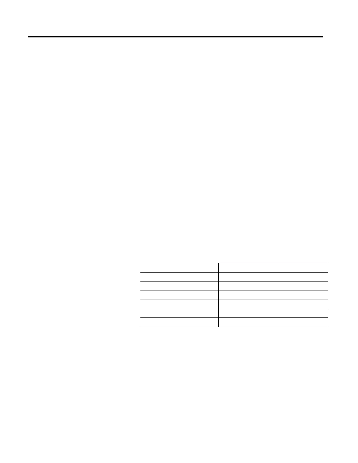
Dynamics Data Parameter Coordinate System Parameters Specification
Speed Vector. Maximum Speed. Primary
Acceleration Vector. Maximum Acceleration. Primary
Deceleration Vector. Maximum Deceleration. Primary.
Orientation Speed Vector Maximum Speed Orientation
Orientation Acceleration Vector Maximum Acceleration Orientation
Orientation Deceleration Vector Maximum Deceleration Orientation
• Coordination Units (1): The speed for 6 parameters (as shown in 1st
Column in table above) are programming units of Coordination Units per
Time Unit, as defined by the Time Units parameter.
 Loading...


