Multi-Axis Coordinated Motion Instructions
Rockwell Automation Publication MOTION-RM002H-EN-P-February 2018 459
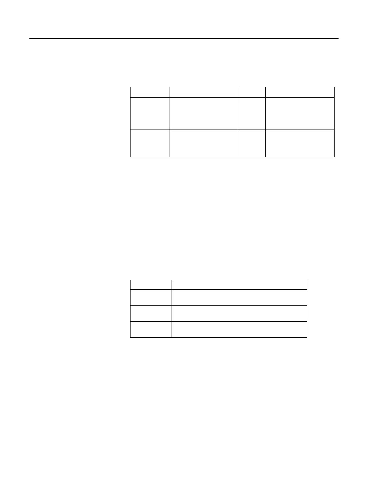
Operands
Ladder Diagram and Structured Text
Operand Type Format Description
Coordinate System COORDINATE_SYSTEM Tag Coordinated group of axes.
Motion Control MOTION_INSTRUCTION Tag Structure used to access instruction
status parameters.
See Structured Text Syntax for more information on the syntax of expressions
within structured text.
Coordinate System
The Coordinate System operand specifies the set of motion axes that define the
dimensions of a Cartesian coordinate system. For this release the coordinate
system supports up to three (3) primary axes. Only the axes configured as primary
axes (up to 3) are included in the coordinate velocity calculations.
Motion Control
The following control bits are affected by the MCSD instruction.
Mnemonic Description
.EN (Enable) Bit 31 The Enable bit sets when the rung transitions from false to true. It resets
when the rung goes from true to false.
.DN (Done) Bit 29 The Done bit sets when the coordinated shutdown is successfully initiated. It
resets when the rung transitions from false to true.
.ER (Error) Bit 28 The Error bit sets when the coordinated shutdown fails to initiate successfully.
It resets when the rung transitions from false to true.
MCSD is a transitional instruction:
• In relay ladder, toggle the Rung-condition-in from cleared to set each time
the instruction should execute.
• In structured text, condition the instruction so that it only executes on a
transition. See Structured Text Syntax.
 Loading...


