Section 1
1 - 7
Figure 1-10 FREESPOOL Arrangement
1 Shifter
2 O-Ring
3 Freespool Piston
4 O-Ring
5 Fitting
11 Washer
13 Gear
14 Capscrew
15 Piston, Freespool Adjust
16 O-Ring
17 Bearing, Cup
18 Cover
19 Bearing. Cone
20 Shaft, Intermediate
21 Gear, Pinion
22 Clutch
23 Setscrew
24 Nut
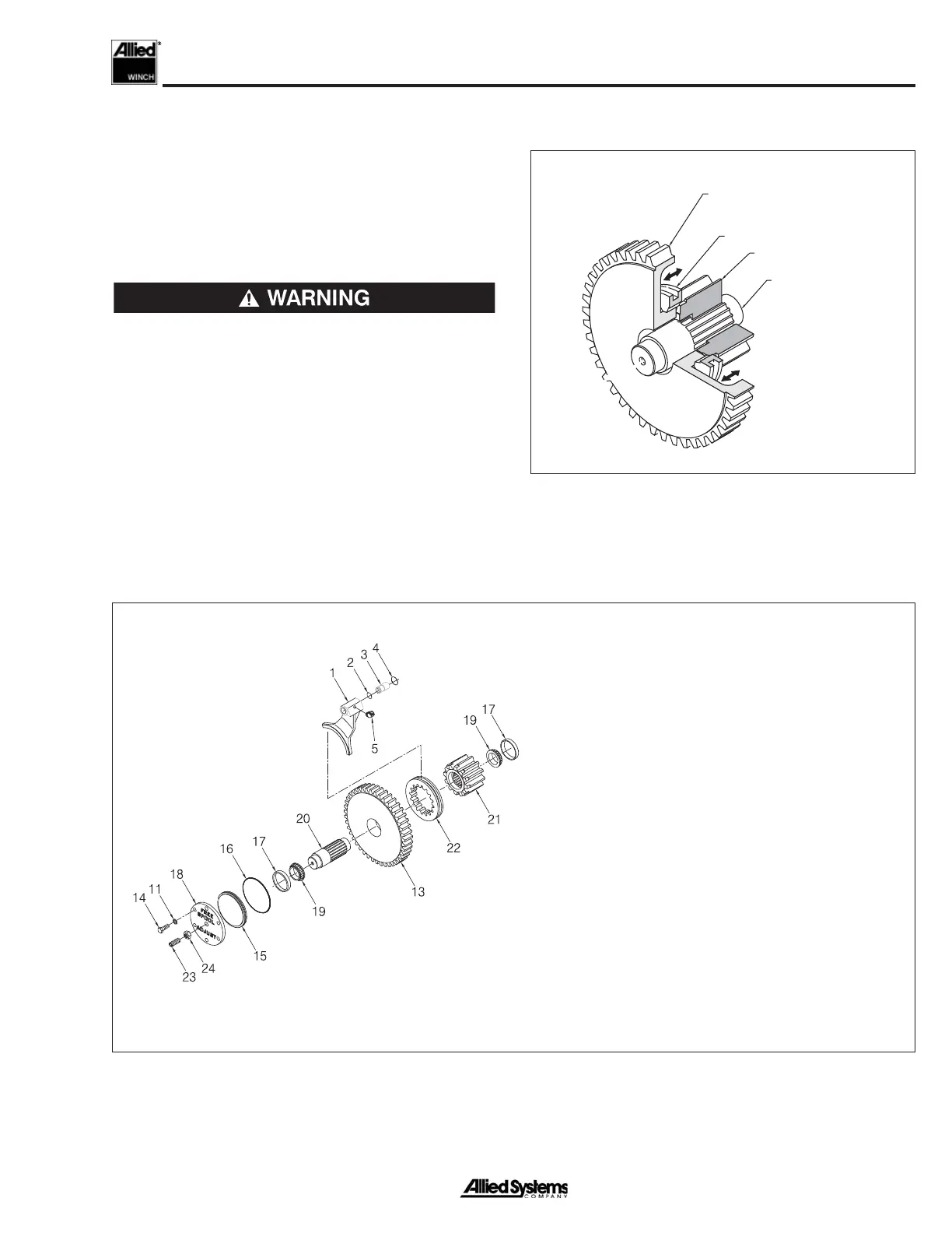
FREESPOOL Operation (See Fig. 1-9 & 1-10)
The FREESPOOL arrangement allows mechanical dis-
engagement of the drum gear from the remainder of the
gear train. When FREESPOOL is selected, a hydraulically-
actuated sleeve disengages the dental clutch from the
intermediate shaft. The drum is now disconnected from
the brake and the winch cannot support a load.
FREESPOOL should not be used if there is a
load on the wire rope. An uncontrolled release
of the load will occur. Loss of the load can
result in injury and/or equipment damage.
The yellow indicator panel on the selector switch lights
when the winch is in FREESPOOL. If equipped with
BRAKE-OFF, the red indicator in the BRAKE-OFF switch
will also light even though that switch is in the off posi-
tion.
NOTE: The dental clutch may not disengage if there
is a load on the wire rope.
Figure 1-9 FREESPOOL Operation
INTERMEDIATE
GEAR
DENTAL CLUTCH
INTERMEDIATE
SHAFT
DRUM PINION
GEAR
 Loading...