Repairs
4 - 24
Brake Disassembly
NOTE: Disassembling the brake while it’s still under its
warranty period immediately invalidates the warranty.
If the brake malfunctions before its warranty period
expires, please contact Allied Systems Company fi rst
before attempting to repair it.
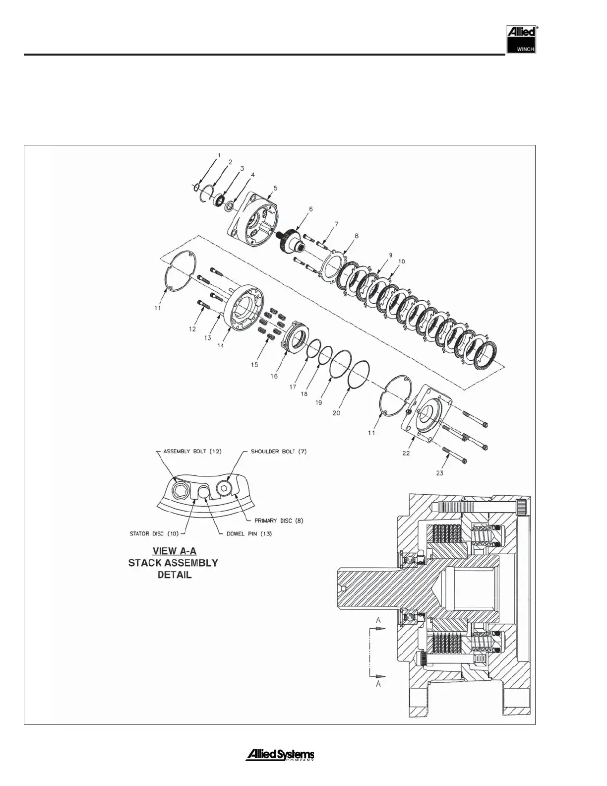
1. Retaining Ring
2. Retaining Ring
3. Bearing
4. Oil Seal
5. Cover Plate
6. Spline Shaft Assembly
7. Socket Head Shoulder Bolts
8. Primary Disc
9. Rotor Disc
10. Stator Disc
11. Case Gasket
12. Capscrew
13. Dowel Pin
14. Spring Plate
15. Spring
16. Piston
17. Back-Up Ring
18. O-Ring
19. Back-Up Ring
20. O-Ring
22. Pressure Plate
23. Socket Head Screw
Note:
The minimum stack height
of discs #9 and #10 is 1.173”.
Figure 4-6 Brake Assembly
- Brake Disassembly
 Loading...