General
1 - 14
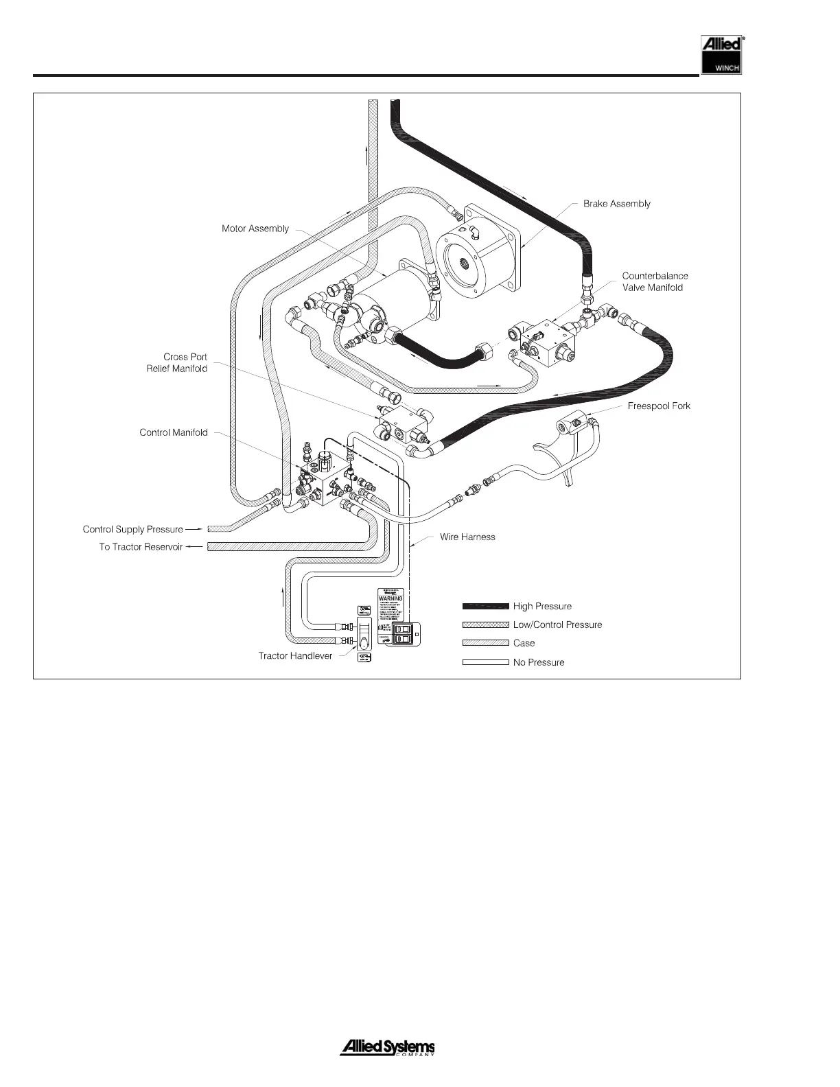
Figure 1-16 Hydraulic System - LINE-IN
Sequence of Operation, Rescue Winch - LINE-IN
The operator pulls back the control lever, which sends
pilot control pressure to the direction control valve and
the brake release valve. Oil fl ows from the pump supply
line into the direction control spool and through a check
valve in the counterbalance valve cartridge. Oil fl ow con-
tinues through to the inlet A port of the hydraulic motor
and builds pressure from the induced load on the winch.
This pressure is communicated to the tractor pump load
sense controller, and the pump displacement is increased
or decreased, depending on the load-induced pressure.
Oil fl ows through the motor, back through the direction
control spool and to the tractor reservoir. Simultaneously,
pilot control pressure at the brake valve is connected to
the brake release port and the brake is fully released. Low
pressure case drain oil fl ows from the hydraulic motor back
to the tractor reservoir.
When pressure on the inlet A port of the motor exceeds
3500 psi, the load sense relief valve opens. The load sense
pressure signal decreases and the tractor pump strokes
back, reducing displacement; consequently, pressure at the
hydraulic motor decreases a corresponding amount.
 Loading...