Section 4
4 - 13
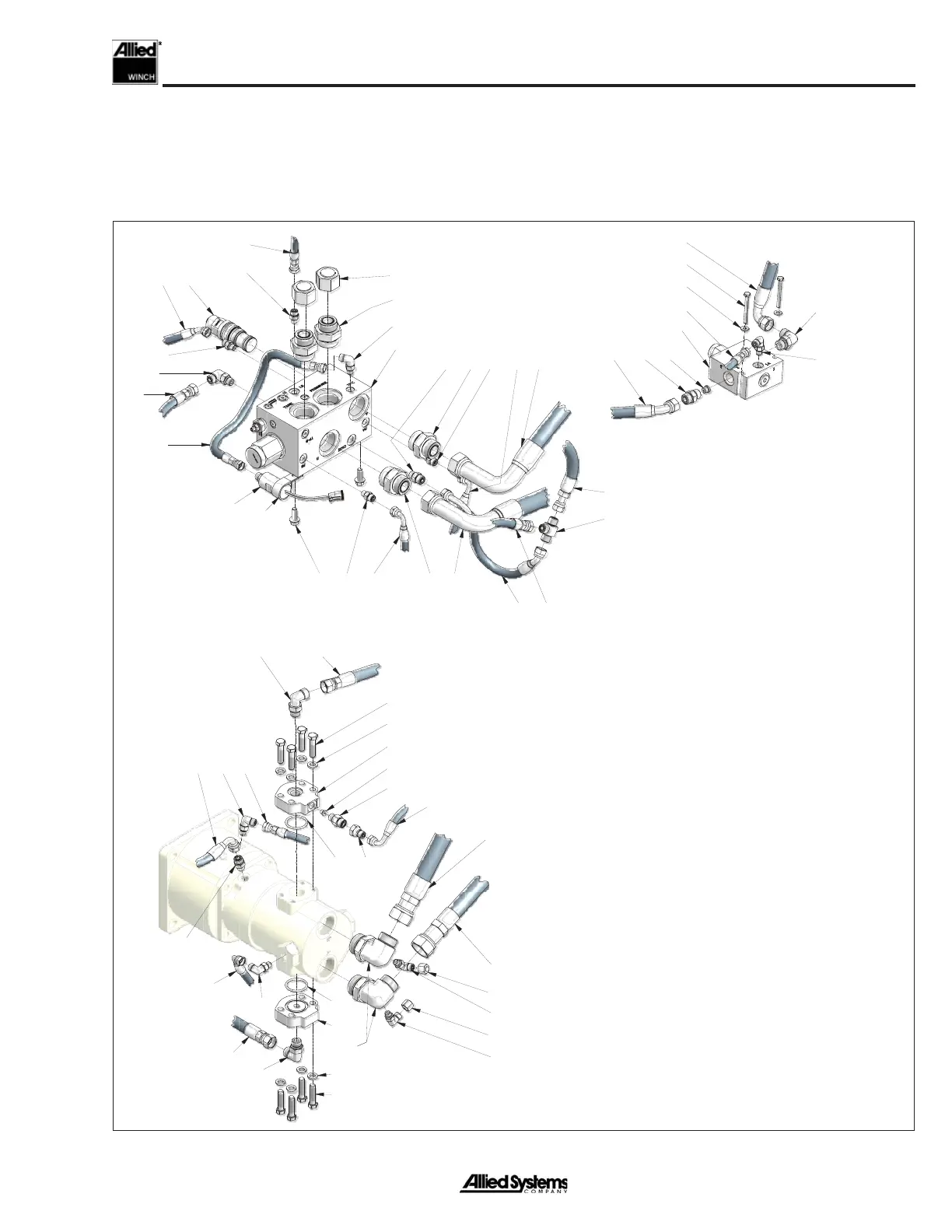
Hydraulic System Disassembly, High-Perfor-
mance Winch
Disconnecting the hoses is necessary in order to remove
the motor shaft assembly. For easier re-installation, be
sure to clearly mark the hose ends of any hoses removed
with their corresponding ports.
Detail at
Directional Manifold
Detail at
Brake-Off Manifold
Detail at
Motor & Brake
1
2
3
5
5
5
5
5
5
6
6
6
7
7
7
7
8
9
8
9
10
10
13
13
17
18
19
20
22
22
23
24
24
25
27
31 32
33
35
35
36
37
38
39
40
41
41
41
42
43
44
44
45
46
46
4748
49
50
51
52
54
54
55
55
56
60
1. Directional Manifold
2. Counterbalance Valve Cartridge
3. Flangescrew
5. Fitting, El
6. Fitting
7. Fitting
8. Hose Assembly, Motor Port B to Directional
Manifold Port B
9. Hose Assembly, Motor Port A to Directional
Manifold Port A
10. Fitting
11. Fitting
12. Hose Assembly, Logic Manifold FS Port to Free-
spool Bulkhead
13. Hose Assembly, Logic Manifold HS Port to Motor
2-Speed Port, Directional Manifold PA Port to
Logic Manifold RI port
14. Hose Assembly, Logic Manifold PP Port to Tractor
Pilot Supply
15. Logic Manifold, Series II
16. Capscrew
17. Fitting, El
18. Hose Assembly, Directional Manifold LS Port to
Tractor Load Sense
19. Hose Assembly, Brake to Logic Manifold BR Port
Figure 4-4 Hydraulic System Components, High-Performance Winch_1
 Loading...