General
1 - 10
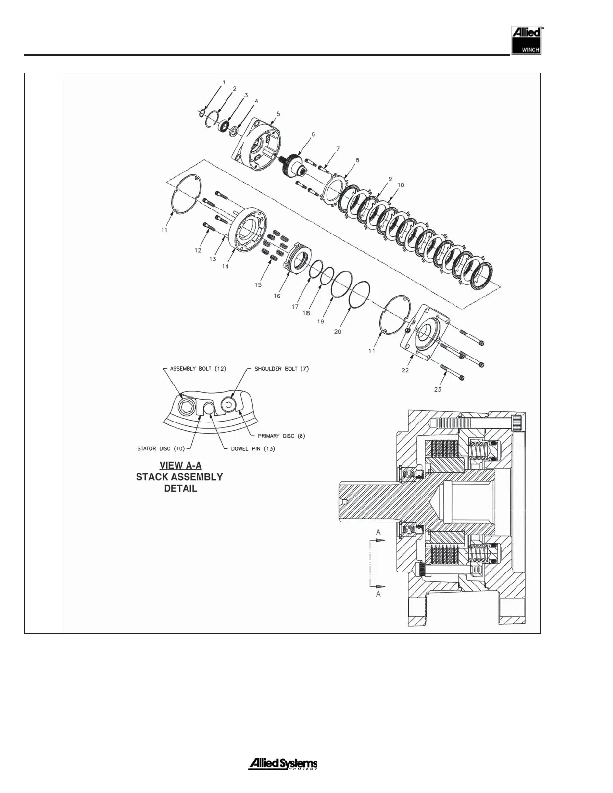
Figure 1-13 Brake
Brake (See Fig. 1-13)
The brake is a dry multi-disc spring applied design. The
springs push against a piston that applies force to the
friction discs and separator plates. The brake valve directs
pressurized oil to the piston and pushes back on the brake
1. Retaining Ring
2. Retaining Ring
3. Bearing
4. Oil Seal
5. Cover Plate
6. Spline Shaft Assembly
7. Socket Head Shoulder Bolts
8. Primary Disc
9. Rotor Disc
10. Stator Disc
11. Case Gasket
12. Capscrew
13. Dowel Pin
14. Spring Plate
15. Springs
16. Piston
17. Back-Up Ring
18. O-Ring
19. Back-Up Ring
20. O-Ring
22. Presure Plate
23. Socket Head Screw
springs to release the brake. The separator plates have
teeth that engage the splines inside the brake housing and
are held stationary. Teeth in the friction discs engage the
splines on the motor shaft and rotate with the hub.
 Loading...